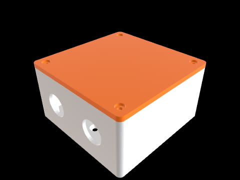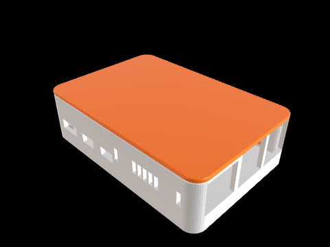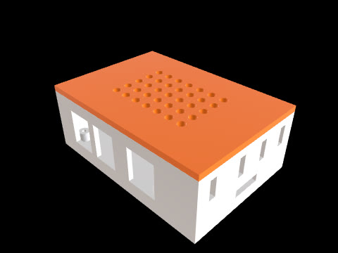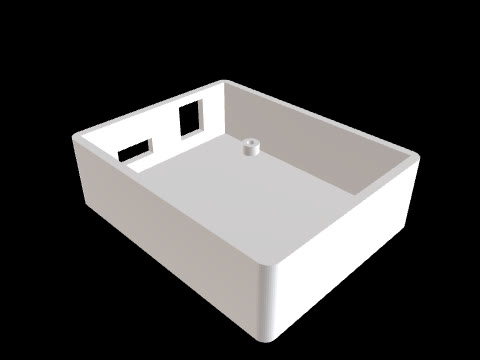
Enclosure for a 70 × 50 mm PCB, with lid
CADlingo generated this model from the prompt below. Open it in the studio to inspect it in 3D and view sections.
The prompt
Enclosure for a 70 x 50 mm prototype PCB, two separate solids: base and lid. Frame: base X=-40..40, Y=-30..30, Z=0..28, walls 2 mm, floor 2 mm, outer vertical edges rounded R3. Inside the base, four standoffs Ø6 x 5 mm tall rise from the floor (Z=2..7) on a 66 x 46 mm pattern centred on the origin, each with a Ø2.5 pilot hole 5 mm deep for M3 screws. The PCB sits on the standoffs at Z=7. The short wall at X=-40 has a 12 x 7 mm rectangular opening for a USB cable centred at Y=0, Z=11. The long wall at Y=-30 has a row of five vent slots 2 x 14 mm, vertical, centred at Z=18, spaced 6 mm along X around X=0. Lid: a 2 mm plate X=-40..40, Y=-30..30, Z=28..30 with the same R3 corners, plus a 2 mm tall locating lip under it (Z=26..28) that fits inside the walls with 0.2 mm clearance per side (lip outer 75.6 x 55.6, 1.5 mm thick).Model facts
- Overall size
- 80 × 60 × 30 mm
- Bodies
- 2
- Volume
- 33.9 cm³
Download
Check the geometry and dimensions in your own CAD tool or slicer before you make or use this part.