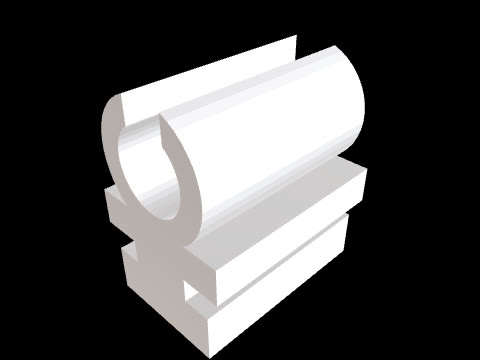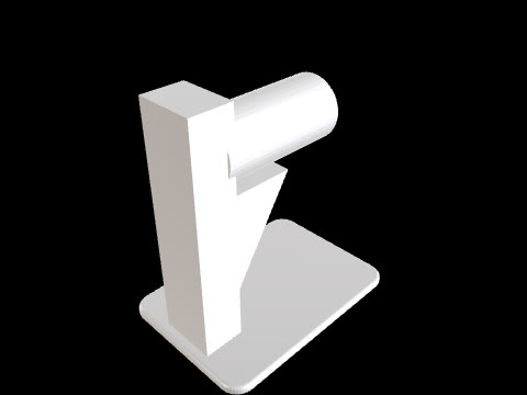
Print-in-place hinge
CADlingo generated this model from the prompt below. Open it in the studio to inspect it in 3D and view sections.
The prompt
Print-in-place hinge, two separate solids that move without assembly. Frame: the hinge axis is X at Y=0, Z=4; the knuckle barrel is Ø8 along X=0..40. Leaf A is a 3 mm plate X=0..40, Y=-30..-4, Z=0..3 joined to knuckles 1, 3 and 5; leaf B is a 3 mm plate X=0..40, Y=4..30, Z=0..3 joined to knuckles 2 and 4. Five knuckles, each 7.2 mm long along X with 0.5 mm gaps between them. Leaf A carries a Ø4 pin through all five knuckles; the knuckles of leaf B have a Ø4.8 bore around the pin (0.4 mm radial clearance). Each leaf has two Ø3.5 countersunk screw holes (90°, Ø7 head) at X=8 and X=32, centred on the leaf width.Model facts
- Overall size
- 40 × 60 × 8 mm
- Bodies
- 2
- Volume
- 7.9 cm³
Download
Check the geometry and dimensions in your own CAD tool or slicer before you make or use this part.