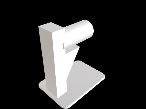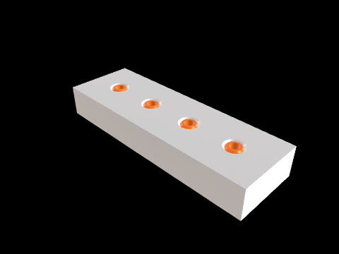
3D printing clearance test
CADlingo generated this model from the prompt below. Open it in the studio to inspect it in 3D and view sections.
The prompt
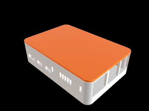
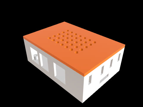
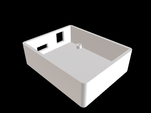
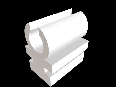
3D printing clearance test coupon, six separate solids: one plate and five loose round pegs printed in place. Frame: plate X=0..80, Y=0..20, Z=0..6. Five Ø10 through holes in the plate along X at X=10, 25, 40, 55, 70, Y=10. In each hole a peg, Z=0..10, with a diameter 10 minus 2 x the clearance, giving radial clearances of 0.1, 0.2, 0.3, 0.4 and 0.5 mm from left to right (peg Ø9.8, 9.6, 9.4, 9.2, 9.0). Each peg has a Ø14 x 1 mm cap at Z=7..8, 1 mm above the plate, so it cannot drop through the hole; the top of the peg Z=8..10 stays plain. Engrave the clearance value (0.1 to 0.5) 0.6 mm deep on the plate top face below each hole at Y=3.5, text height 3.Model facts
- Overall size
- 80 × 20 × 10 mm
- Bodies
- 6
- Volume
- 11.1 cm³
Download
Check the geometry and dimensions in your own CAD tool or slicer before you make or use this part.