
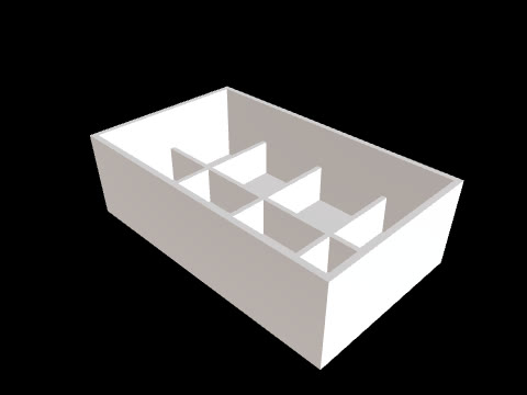
An enclosure can look spacious from the outside while its ribs divide the space you need for a circuit board. Before changing its size, look inside.
This guide uses the saved electronics enclosure in the CADlingo examples gallery. You can open that specific model rather than asking for a new generation. The original request asks for a 100 × 60 × 30 mm enclosure with 2 mm walls, internal ribs and draft angles.
Open the saved example
Use the link below to open the enclosure in Studio. Rotate it until the open top and the intersections between the ribs are visible. Start by comparing the actual model with the original request.
The dimensions in a request describe the intended result. They are not a substitute for checking the exported geometry.
Open the enclosure exampleCheck the space your components would occupy
Look at the rib grid and the spaces it creates. Decide where a board, connector or cable would go, and whether a rib occupies that space. Use a section view when an exterior view hides the area you need to inspect.
This saved model has an open top. A lid, board supports and connector openings are separate requirements to specify if your enclosure needs them. A plausible outer silhouette does not answer those questions.
Read the controls before moving them
This example exposes Wall thickness and Draft angle. The sliders suggest wall thickness from 1 to 3 mm and draft angle from 1 to 2 degrees; you can also enter a value directly. Other values in the model are not all exposed as controls.
A wall-thickness change is not the same as making more room inside. In this model, the nominal outer envelope is fixed in the source, so increasing the wall thickness reduces the cavity width and depth. The floor thickness is a separate, fixed value.
Change one available parameter at a time, then inspect the result again. Check the cavity and the places where ribs meet the walls.
Describe what should change and what should stay
For a change beyond the available controls, name the feature and the dimensions or locations to preserve. For example, if a rib crosses the space intended for your board, a follow-up request could be:
Remove the rib that crosses the board area. Keep the outer dimensions and wall thickness unchanged. Ask me to identify the rib if its location is unclear.
Compare the next result with the previous one
After a revision, inspect both the requested change and the features that were supposed to stay the same. Look for the removed or changed rib, check the remaining connections, and confirm the dimensions that matter to your application.
The request above is an example of how to describe a change, not a recorded before-and-after result. Selecting a part for inspection should not be treated as a guarantee that a later text edit affects only that part.
Check the exported file in your next tool
Open the export in the CAD tool or slicer you intend to use. Confirm units, overall dimensions and internal clearances there before making a part. Available export formats depend on your plan; the current options and credit terms are on the pricing page.
CADlingo is in beta. This enclosure is a starting point for exploring a design. Its rib layout and draft controls do not establish that it is ready for injection molding or that it will fit your electronics. Those decisions need checks against the actual components and manufacturing process.