
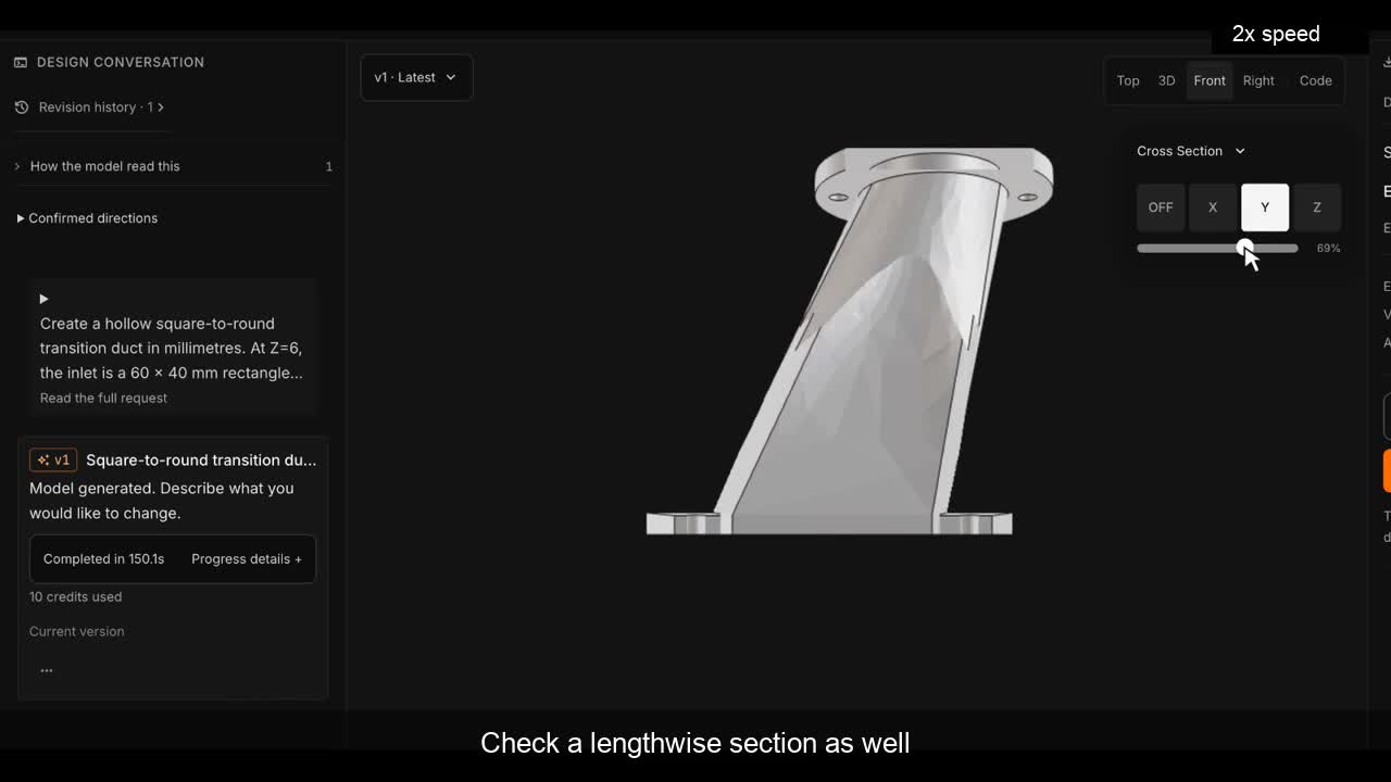
A 60 × 40 mm inlet, a 40 mm round outlet, and an offset between them. This CADlingo session turns that request into a hollow transition with two mounting flanges. The useful part of the review is looking inside, rather than judging only the exterior.
Describe positions as well as sizes
The inlet is centred at X=0, Y=0 at Z=6 mm. The outlet is centred at X=30, Y=15 at Z=100 mm. Giving both positions makes the offset explicit. The request also defines the flange thicknesses and hole patterns, and asks for one connected solid.
This is the exact English request used in the October 12 session. The 2 mm wall is a nominal requirement measured in XY sections; it is not a claim that every sloping surface has a constant 2 mm normal thickness.
Create a hollow square-to-round transition duct in millimetres. At Z=6, the inlet is a 60 × 40 mm rectangle centred at X=0, Y=0. At Z=100, the outlet is a 40 mm diameter circle centred at X=30, Y=15. Connect them with a smooth, continuously open loft. Use nominal 2 mm walls measured in each XY section. Add a 100 × 70 × 6 mm bottom flange with the rectangular opening and four 5.5 mm through-holes at X=±42, Y=±27. Add a 70 mm outside-diameter top flange from Z=100 to 106, with the 40 mm opening and four 5.5 mm holes on a 56 mm pitch circle. Keep the duct and both flanges as one connected solid. Expose the offsets and supported dimensions for editing.
Move a section through the model
After generation, we rotated the result, opened the cross-section controls and moved a Z cut through the duct. After downloading STEP, we continued inspecting the same model from above and with a lengthwise Y section. The recording preserves that order.
The top cut reveals the rectangular opening and how the passage changes toward the round end. The lengthwise cut shows the interior along the transition. Moving the cut helps reveal features that a single exterior view can hide. A section view is a visual inspection aid, not a flow or strength test.
Check the downloaded geometry
We reopened the exported STEP. It contained one valid solid with overall bounds of 115 × 85 × 106 mm. The bounds include both flanges and the offset; they are not the inlet dimensions.
Finite probes checked the lower and upper openings, five points along the passage centreline, flange material, both four-hole bolt patterns and two wall samples near the ends. Those recorded checks passed. They do not establish every surface tolerance or wall thickness throughout the loft.
Use the result as a starting point
For your own transition, define the two openings, their positions, the attachment interfaces and the wall requirement first. Then rotate the result, move sections through it and inspect the exported geometry before deciding what to change.
We did not test airflow, pressure loss, loading, sealing or manufacturing suitability. Those depend on the application, material and process. STEP download requires an eligible paid plan; see pricing for current access and promotion terms.
Check current plans and export access