
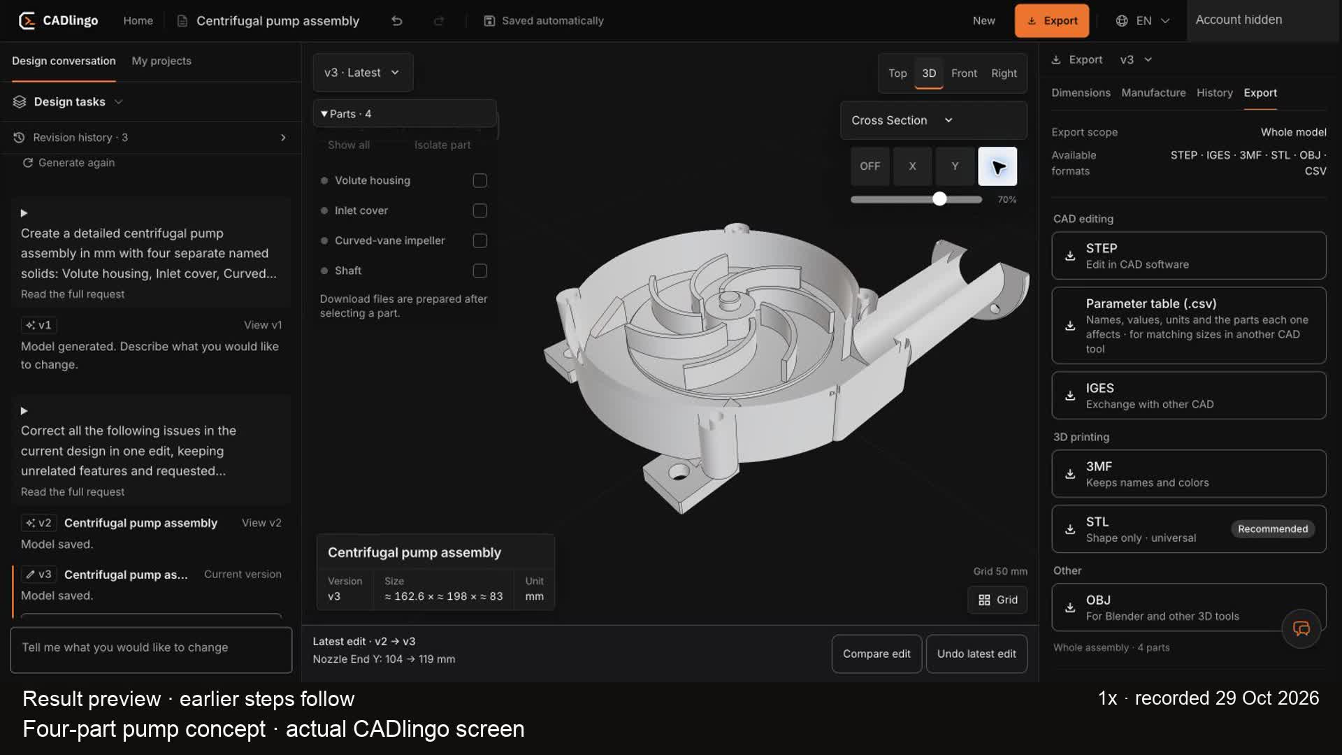
We described a centrifugal pump in CADlingo, extended its outlet by 15 mm, and saved the edit. A section view revealed the curved vanes inside the housing. We reopened the project to check that the change remained.
The result is a geometry concept with four separate solids: a volute housing, an inlet cover, an impeller and a shaft. It is a starting point for further design, not a tested pump.
Start with the details that matter
Our accepted prompt asked for a four-part assembly in millimetres. It specified a 100 mm impeller with seven backward-swept curved vanes, a hollow housing with an expanding spiral collector, an inlet cover and a separate shaft. It also asked for editable dimensions and an outlet with a flange.
The request separated the intended parts and described how they should relate to one another. It also called the model a geometry concept, leaving room for later engineering work.
Create a detailed centrifugal pump assembly in mm with four separate named solids: Volute housing, Inlet cover, Curved-vane impeller, Shaft. This is a geometry concept. Shaft axis Z, impeller centered at X=Y=0. Open impeller OD100: 3mm backplate, hub OD24 with bore10, seven 2.5mm thick blades rising 12mm above the backplate. Each blade must have a genuinely smooth backward-swept curved planform from the inlet-eye region to the rim, not a straight radial plate. Blend blade roots where feasible. Housing: real hollow rotor chamber plus a progressively expanding spiral collector with a cutwater, continuously joining a tangential outlet. Leave at least 2mm clearance around rotating parts. Floor and walls 4mm. Tangential nozzle clear bore25; end flange OD54, thickness6, four diameter5.5 bolt holes on PCD42. Bore connects to the collector. Add integrated mounting feet with bolt holes and reinforcing ribs. The housing must be hollow and the spiral passage must expand, not be a solid snail block or a simple circular ring. Separate removable inlet cover, 6mm thick, with centered through inlet36 and raised inlet collar. Matching cover/housing fastener holes. Keep an open path from inlet to impeller eye. Separate shaft10 through the hub, with clearance through the rear housing. Assemble the four solids in their correct positions; do not fuse separate components. Keep key sizes as named editable parameters. Use reasonable editable defaults for unstated sizes. Finish exposed outside edges with small chamfers or fillets where feasible.
The first, longer request returned a generic error. We shortened it and submitted the accepted request above. The video omits that unsuccessful submission.
Inspect the shape, including the interior
The saved assembly has four named parts in CADlingo. We inspected the impeller and housing separately and used a section view to look inside the assembly. The section exposes the curved vanes and the surrounding housing geometry.
We also inspected the downloaded STEP geometry. It contained four valid solids. In this file, the six pairs of components had no positive-volume intersection. The measured minimum geometric distance between housing and impeller was 2 mm. Sample points along the inlet and outlet were clear of housing material.
These are specific checks on this model. Sample points do not establish that every passage is open, and static geometry does not establish running clearance or flow performance.
Edit the saved model
After inspection, we changed the Nozzle End Y parameter from 104 mm to 119 mm. This extended the housing outlet by 15 mm. We applied the edit and saved revision v3.
A comparison of the downloaded v2 and v3 STEP files showed a change to the housing geometry. The cover, impeller and shaft showed zero geometric difference in both comparison directions. We reopened the project and confirmed that v3 retained the 119 mm value.
Before the numeric edit, we also tried an AI-suggested repair. That attempt saved v2, but the STEP comparison showed no geometric change. It is not shown in the edited video and should not be treated as a successful repair.
What this example does—and does not—show
The retained v3 STEP file provides a way to examine the resulting geometry further.
We did not print or physically assemble the model, run fluid tests, or validate its performance or manufacturability. Drive support, shaft sealing, mounting integration, tolerances and materials need further design and testing. Before fabrication or use, review the geometry and engineering requirements for the intended application.