Slider-crank mechanism
CADlingo generated this model from the prompt below. Open it in the studio to inspect it in 3D, view sections and try its dimension controls.
The prompt
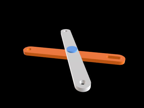
Model an in-line slider-crank mechanism, assembled at one crank angle, as 4 separate solids: crank, connecting rod, slider and guide. Frame: the crank axis is parallel to Y through X=10, Z=5. The slider moves along the line parallel to X through Z=5 (in line with the crank axis). Angles are measured in the XZ plane from +X toward +Z. Crank (one solid): hub Ø30 on the crank axis from Y=-16 to Y=0; arm Y=0..8, a straight 24 wide bar from the crank axis to the crank-pin centre 25 away, both ends rounded R12 about those two centres; crank pin Ø10 from Y=8 to Y=15. Ø12 bore on the crank axis through Y=-16..8 with a 4 wide keyway pointing away from the crank pin (230°), floor 7.8 from the axis. Position: the crank points at 50°, so the crank-pin centre is at X=26.070, Z=24.151. Connecting rod: Y=8.2..14.2, 80 between centres. Big eye Ø24 with a Ø10.2 hole on the crank pin; small eye Ø18 with a Ø8.2 hole on the wrist pin; the eyes are joined by a straight shank 10 wide centred on the line between the centres. Slider (one solid, wrist pin included): the wrist-pin centre is on the slide line at X=103.744 (so the rod length is exactly 80). Block X=87.744..119.744 (wrist pin -16..+16), Z=-6..16, Y=2..20. A slot for the rod, Y=7.7..14.7, runs through the full block height and from the block's -X face to X=114.744 (wrist pin +11), leaving a 5 thick bridge at the +X end. Wrist pin Ø8 along Y from Y=2 to Y=20 on the wrist-pin centre, bridging the slot. Guide (one solid): base plate X=60..150, Y=-6..28, Z=-16..-6 (the slider rests on its top face Z=-6), and two side walls X=60..150, Z=-6..8, at Y=-6..2 and Y=20..28, touching the slider's Y=2 and Y=20 faces.
Model facts
- Overall size
- 155 × 44 × 52.2 mm
- Bodies
- 4
- Volume
- 84.0 cm³
- Adjustable in the studio
- 3 dimensions