Scissor link, 3 parts
CADlingo generated this model from the prompt below. Open it in the studio to inspect it in 3D, view sections and try its dimension controls.
The prompt
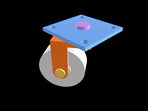
Model a scissor link, assembled, as 3 separate solids: bar A, bar B and the pivot pin. Frame: the pivot axis is parallel to Z through X=15, Y=20. Angles in the XY plane from +X toward +Y. Distances along a bar are measured from the pivot axis along that bar's direction. Both bars have the same stadium outline in plan: 16 wide, straight sides, semicircular ends of radius 8 centred at -60 and +60 along the bar (overall length 136), with a Ø8.2 pivot hole on the pivot axis. Bar A: 5 thick, Z=0..5, its direction points at 35°. It has a Ø6.2 hole at -60 and, at the + end, a slot 6.2 wide along the bar with semicircular ends whose centres are at +48 and +60. Bar B: 5 thick, Z=5.2..10.2 (0.2 above bar A), its direction points at 145°, so the bars cross at 110°. It has Ø6.2 holes at -60 and +60. Pivot pin: Ø8 shank on the pivot axis from Z=-4 to Z=10.2, head Ø14 from Z=10.2 to Z=12.2 seated on bar B's top face, and a Ø2.5 split-pin hole through the shank along the X direction at Z=-1.5.
Model facts
- Overall size
- 114.3 × 84.8 × 16.2 mm
- Bodies
- 3
- Volume
- 20.7 cm³
- Adjustable in the studio
- 3 dimensions