Tie-rod hydraulic cylinder
CADlingo generated this model from the prompt below. Open it in the studio to inspect it in 3D, view sections.
The prompt
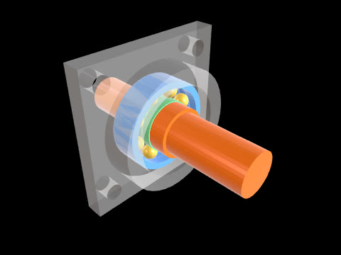
Model a tie-rod hydraulic cylinder as eight separate solids: base cap, barrel, head cap, piston-and-rod (one solid) and four tie rods. Frame: the cylinder axis is parallel to X through Y=20, Z=35. Offsets 'u, v' below are Y and Z measured from that axis (Y = 20 + u, Z = 35 + v). Base cap: square block X=0..20, u, v = -40..40, with a spigot Ø60 from X=20 to X=25 entering the barrel. Port: a Ø10 hole drilled from the top face (v=40) straight down at X=10, u=0, to the axis, and a Ø8 axial passage on the axis from X=10 to X=25 (opening into the bore). Barrel: tube Ø70 outside, Ø60 inside, X=20..170. Head cap: square block X=170..190, u, v = -40..40, spigot Ø60 from X=165 to X=170, rod bore Ø25 through. Tie-rod holes: both caps have four Ø10 holes along X at (u, v) = (±30, ±30). Piston and rod (one solid): piston Ø60 from X=85 to X=105 (so the piston's base-side face is 60 from the spigot face X=25); rod Ø25 from X=105 to X=250 through the head cap; a Ø12 cross hole through the rod along Z at X=240. Tie rods (four, identical): Ø10 from X=0 to X=190 on (u, v) = (±30, ±30), with heads Ø17 from X=-5 to X=0 and from X=190 to X=195 bearing on the outer faces of the caps.
Model facts
- Overall size
- 255 × 80 × 80 mm
- Bodies
- 8
- Volume
- 602.6 cm³