
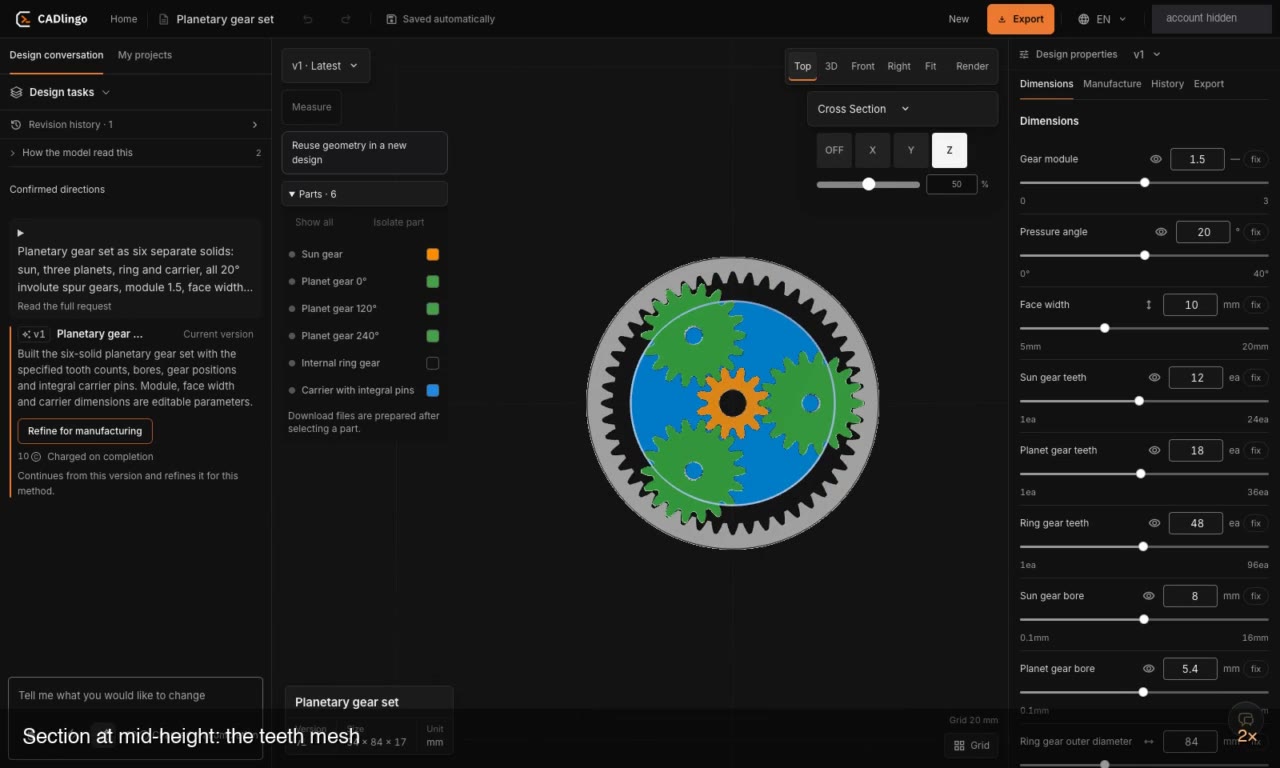
A gear set and a manifold need different checks. A section through the gears shows how the teeth line up. A section through the manifold reveals the channel hidden inside the block.
We prepared six online demos for the week of Formnext 2026. Each model started with a written brief. We exported the final versions as STEP and checked the geometry that mattered for each example. For additive manufacturing, these checks help spot blocked passages and overlapping parts before slicing.
Planetary gear set
The module 1.5 gear set has six solids: a 12-tooth sun, three 18-tooth planets, a 48-tooth ring and a carrier. The planet pins sit 22.5 mm from the center, 120° apart.
We used a section at mid-height to inspect the teeth and checked the exported solids for overlap. The 3MF export also retains the colors assigned to the parts.
Open this model in StudioManifold with a curved internal channel
Inside the 60 × 40 × 30 mm block, a Ø6 mm channel bends 90° on a 15 mm centerline radius. A Ø4 mm branch joins the main channel.
A section shows the bend from the side. We checked 22 points in the STEP model, including points in the channel, its walls, the branch and the mounting holes. Studio also exported the section as a 2D DXF.
Open this model in StudioRaspberry Pi 5 enclosure
The 91 × 62 × 26 mm case has a base and a snap-on lid. The base uses a 58 × 49 mm mounting-hole pattern and has openings for the USB-C, micro-HDMI, Ethernet and USB ports.
Studio flagged an overlap between the vent slots and the snap pockets. We used “Repair this item” to move the affected slots and save version 2. We checked the connector openings against the design brief. Fit with a physical board remains to be tested.
Open this model in StudioV-block drill jig
A 90° V-groove locates a Ø25 mm round bar. Two Ø6 mm guide holes reach the groove, and two M5 clearance holes secure the jig.
The section shows where the guides meet the groove. We then changed the counterbore diameter from 10 to 10.4 mm in Studio and saved version 2.
Open this model in StudioGripper jaw pair
We revised the brief to use a 120° V-notch, 5 mm deep, on each mirrored jaw. The final STEP checks covered the notches, the gap between the jaws and the M4 mounting holes.
The usable grip range depends on the gripper travel and contact with the workpiece. Confirm both with the intended mechanism.
Open this model in StudioTwo-piece pipe clamp
The two halves form a Ø32 mm bore with a 1 mm clamping gap. We checked the gap and sampled the bore and Ø6.6 mm bolt holes to confirm their placement in the exported model.
Open this model in StudioChecks before fabrication
Open any example in Studio and use the section view to inspect the features that matter for your design. Check fit, strength and process settings before you print or machine the part.