
실제 생성 결과
CADlingo가 만든 모델을 직접 열어 보세요
CADlingo로 생성한 저장 모델을 살펴보세요. 스튜디오에서 형상과 단면을 확인하고 모델에 제공되는 치수 조절 기능을 사용할 수 있습니다.
모델 85개
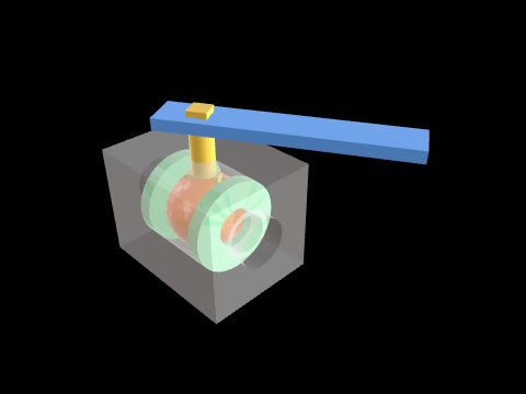
“레버식 볼밸브를 30° 열린 상태로, 분리된 솔리드 6개(몸체, 볼, 시트 링 2개, 스템, 핸들)로 만들어줘. 좌표계: 유로 축 = X축, 볼 중심 = 원점, 스템 축 = Z축. 방향 d = (cos30°, sin30°, 0) = (0.86603, 0.5, 0) 은 볼 구멍과 핸들 방향, e = (-0.5, 0.86603, 0) 은 그에 수직인 수평 방향. (1) 몸체 (한 솔리드): 블록 X=-40~40, Y=-30~30, Z=-30~30. 유로 구멍 Ø20이 X방향 전장 관통, 양 끝에 배관용 카운터보어 Ø26 (X=30~40, X=-40~-30). 내부 캐비티: X축 위 원통 Ø48, X=-22~22 (닫힌 공간). 스템 구멍 Ø12가 Z축 위 캐비티에서 윗면 Z=30까지. (2) 볼: 구 Ø40 (중심 원점). 볼 구멍 Ø20이 d 방향 축으로 관통. 윗면에 스템 탱 홈: d 방향으로 길고, e 방향 폭 6 (±3), Z=15에서 구 표면까지 (d 방향으로 전장 관통). (3) 시트 링 2개: 각각 X축 위 환형 원통 외경 Ø48, 내경 Ø20, 하나는 X=15~22, 다른 하나는 X=-22~-15. 볼과 닿는 쪽은 볼 구면(Ø40)으로 깎여 볼에 맞닿는다. (4) 스템 (한 솔리드): 탱 = d 방향 길이 16 (±8), e 방향 두께 6 (±3), Z=15~21인 직육면체 (볼의 홈 안). 축 Ø12가 Z=21~45. 윗끝 사각 10×10 (변은 d, e 방향과 평행)이 Z=45~55. (5) 핸들 (한 솔리드): Z=46~52의 판. 스템 축 기준 d 방향으로 -20부터 +100까지, e 방향 폭 20 (±10), 스템 사각이 끼는 10×10 사각 구멍 (변은 d, e와 평행). 즉 핸들은 볼 구멍과 같은 30° 방향을 가리킨다.”
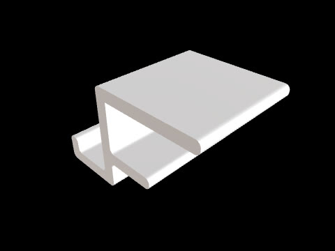
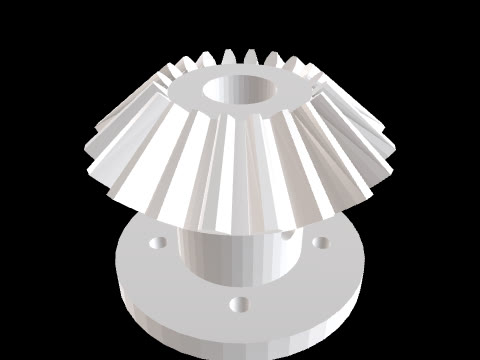
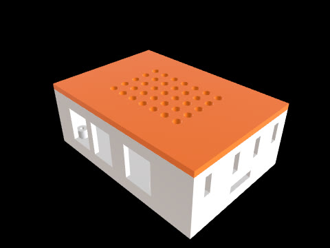
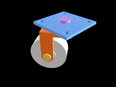
“Model a swivel caster as seven separate solids: top plate, thrust washer, kingpin bolt, nut, fork, wheel, axle. Frame: the kingpin (swivel) axis is the Z axis; the floor is Z=0 and the wheel touches it. Top plate: X=-40..40, Y=-40..40, Z=100..105 (edges parallel to X and Y), Ø12 hole on the Z axis and four Ø9 holes at (±30, ±30), all through along Z. Thrust washer: Ø40, bore Ø12, Z=92..100, on the Z axis. Kingpin bolt: shank Ø12 from Z=78 to Z=105 on the Z axis, head Ø20 from Z=105 to Z=110. Nut: Ø20 cylinder, bore Ø12, Z=78..84. Fork, one solid, described in a fork frame whose origin is on the Z axis: its x axis is the horizontal direction (cos35°, sin35°, 0), its y axis is (-sin35°, cos35°, 0), z = world Z. Crown plate: x=-42..15, y=-23..23, Z=84..92, with a Ø12 hole on the Z axis. Two legs, 5 thick, at y=18..23 and y=-23..-18; each leg (in the x-Z plane) is the rectangle x=-42..-18, Z=37.5..84 united with a disc R12 centred on the axle point (x=-30, Z=37.5), and has a Ø10 axle hole there. So the axle sits 30 behind the kingpin toward the 215° direction, at world (X, Y) = (-24.575, -17.207), Z=37.5. Wheel: axis along the fork y axis through the axle point. Tyre Ø75 over y=-15..15, hub Ø30 over y=-18..18 (the hub faces touch the legs), bore Ø10. Axle: Ø10 along the fork y axis from y=-26 to y=26 through the legs and wheel, with Ø16 heads over y=23..26 and y=-26..-23 bearing on the outer faces of the legs.”
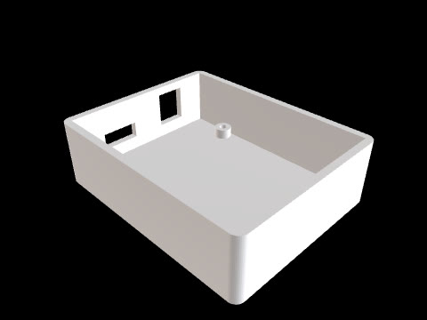
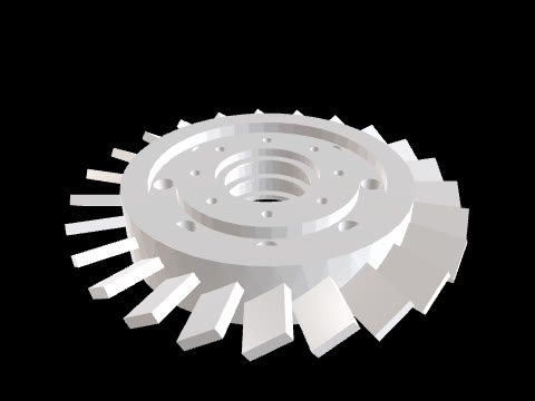
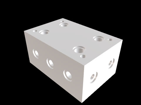
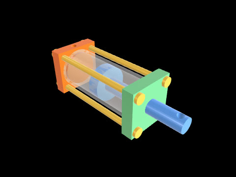
“Model a tie-rod hydraulic cylinder as eight separate solids: base cap, barrel, head cap, piston-and-rod (one solid) and four tie rods. Frame: the cylinder axis is parallel to X through Y=20, Z=35. Offsets 'u, v' below are Y and Z measured from that axis (Y = 20 + u, Z = 35 + v). Base cap: square block X=0..20, u, v = -40..40, with a spigot Ø60 from X=20 to X=25 entering the barrel. Port: a Ø10 hole drilled from the top face (v=40) straight down at X=10, u=0, to the axis, and a Ø8 axial passage on the axis from X=10 to X=25 (opening into the bore). Barrel: tube Ø70 outside, Ø60 inside, X=20..170. Head cap: square block X=170..190, u, v = -40..40, spigot Ø60 from X=165 to X=170, rod bore Ø25 through. Tie-rod holes: both caps have four Ø10 holes along X at (u, v) = (±30, ±30). Piston and rod (one solid): piston Ø60 from X=85 to X=105 (so the piston's base-side face is 60 from the spigot face X=25); rod Ø25 from X=105 to X=250 through the head cap; a Ø12 cross hole through the rod along Z at X=240. Tie rods (four, identical): Ø10 from X=0 to X=190 on (u, v) = (±30, ±30), with heads Ø17 from X=-5 to X=0 and from X=190 to X=195 bearing on the outer faces of the caps.”
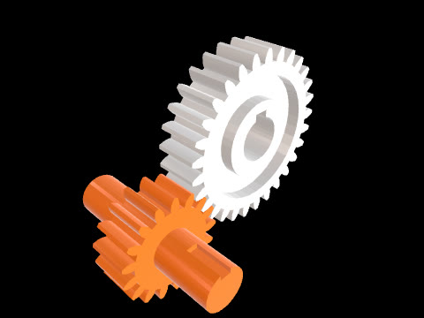
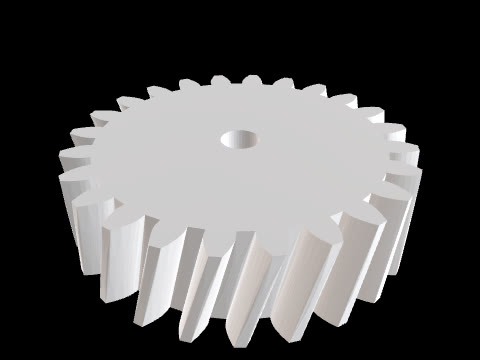
“Model a meshing spur gear pair as two separate solids. Frame: both gear axes are parallel to the X axis. The pinion axis passes through Y=20, Z=-10; the wheel axis passes through Y=99.674, Z=36, so the line of centres runs 30° from +Y toward +Z (centre distance 92). Angular positions about each axis are measured in the YZ plane from +Y toward +Z. Tooth form for both: involute, module 4, pressure angle 20°, no profile shift, addendum 1.0m, root diameter = pitch diameter - 2.5m, root fillets free. Backlash: circular tooth thickness on the pitch circle = pi*m/2 - 0.15 = 6.133, symmetric about the tooth centre line. Both toothed widths span X=0..30. Pinion (a gear shaft, one solid): 17 teeth, pitch Ø68, outside Ø76, root Ø58. Shaft Ø30 from X=-50 to X=0 and from X=30 to X=75. The X=30..75 end has a square-ended keyway 8 wide from X=48 to X=75 on the 90° side (+Z side of the shaft), floor 11 from the pinion axis. Phase: the pinion has a tooth SPACE centred on the 30° direction (toward the wheel). Wheel: 29 teeth, pitch Ø116, outside Ø124, root Ø106. Both side faces are recessed: an annular pocket from Ø56 out to Ø88, 9 deep, is cut into the X=0 face (X=0..9) and into the X=30 face (X=21..30), leaving a web X=9..21. Hub Ø56 from X=-10 to X=30 (it sticks out 10 on the -X side). Ø32 bore through X=-10..30 with a 10 wide keyway on the 90° side over the full length, keyway floor 20.3 from the wheel axis. A radial Ø6.8 set-screw hole at X=-5 runs from the hub surface into the bore on the 0° side (+Y side). Phase: the wheel has a TOOTH centred on the 210° direction from its own axis (toward the pinion), which sits in the pinion's tooth space.”
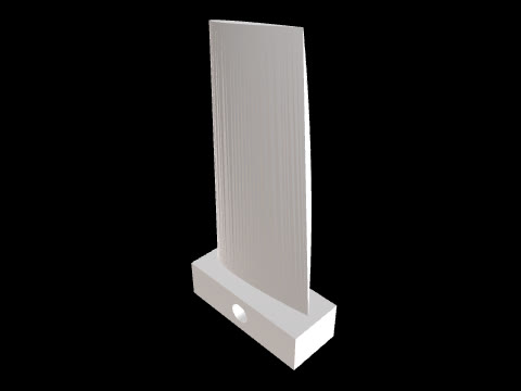
“NACA 대칭 익형 단면 3개를 로프트한 비틀린 블레이드와 루트 블록을 단일 솔리드로 만들어줘. 좌표계: 블레이드 스팬 방향 = +Z, 비틀림 축 = Z축 (각 단면의 1/4 시위점이 Z축 위에 있다). 단면 정의 (단면 평면 Z=z 안의 국부 좌표 x, y): 시위선은 국부 x축 위, 앞전(LE)은 x = -c/4, 뒷전(TE)은 x = 3c/4. 두께 분포는 NACA 4자리 대칭식 y = ±5·t·c·(0.2969·√ξ - 0.1260·ξ - 0.3516·ξ² + 0.2843·ξ³ - 0.1036·ξ⁴), ξ = (x + c/4)/c (0~1), 뒷전은 뾰족하게 닫힌다. 국부 좌표는 +Z에서 내려다볼 때 반시계 방향으로 비틀림각만큼 돌린 뒤 월드에 놓는다 (국부 x축 = (cosθ, sinθ, 0)). - 단면 1: Z=0, 시위 c=60, 두께비 t=0.15 (NACA 0015), 비틀림 θ=0°. - 단면 2: Z=60, c=48, t=0.12 (NACA 0012), θ=15°. - 단면 3: Z=120, c=36, t=0.10 (NACA 0010), θ=30°. 블레이드 = 세 단면을 순서대로 지나는 매끄러운 로프트 (Z=0~120, 끝은 평평). 루트 블록: X=-20~50, Y=-14~14, Z=-20~0 직육면체 (블레이드 루트 면이 그 윗면에 붙는다), Y방향 관통 Ø10 구멍, 축 (X=15, Z=-10).”
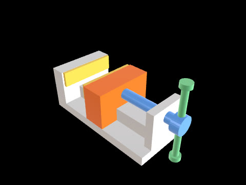
“벤치 바이스를 조립 상태의 분리된 솔리드 6개(몸체, 이동 조, 고정 조 판, 이동 조 판, 스크루, 핸들)로 만들어줘. 좌표계: 조(jaw)가 X방향으로 움직이고, 스크루 축은 X축과 평행한 (Y=0, Z=45) 직선. 바닥면 Z=0. (1) 몸체 (한 솔리드): 베이스 판 X=-60~100, Y=-40~40, Z=0~12. 고정 조 블록 X=-60~-40, Y=-40~40, Z=12~60. 가이드 바 X=-40~90, Y=-15~15, Z=12~30. 엔드 판 X=90~100, Y=-25~25, Z=12~60, 스크루 축 위에 Ø14 구멍이 X방향 관통. (2) 고정 조 판: X=-40~-36, Y=-38~38, Z=40~60 (고정 조 블록의 +X면에 붙는다). (3) 이동 조 (한 솔리드): 블록 X=5.5~35.5, Y=-40~40, Z=12~60에서 가이드를 감싸는 채널 Y=-15~15, Z=12~30을 X방향 전장으로 뺀 형상 (채널 윗면이 가이드 윗면 Z=30에, 옆면이 가이드 옆면에 닿는다). +X면(X=35.5)에서 스크루 축 위로 Ø14 막힌 구멍, 깊이 12 (X=23.5~35.5, 바닥 평평). (4) 이동 조 판: X=1.5~5.5, Y=-38~38, Z=40~60 (이동 조의 -X면에 붙는다). 따라서 두 조 판 사이 벌림(X=-36~1.5)은 37.5. (5) 스크루 (한 솔리드, 나사산은 생략한 원통): Ø14가 X=23.5~110 (끝이 이동 조 막힌 구멍 바닥에 닿고 엔드 판 구멍을 지난다), 머리 Ø24가 X=110~122. 머리에 X=116에서 Z방향 Ø8 관통 구멍. (6) 핸들 (한 솔리드): Ø8 봉이 머리 구멍을 지나 Z방향으로, 축 (X=116, Y=0), Z=0~90. 양 끝에 노브 Ø14: Z=-6~0과 Z=90~96.”
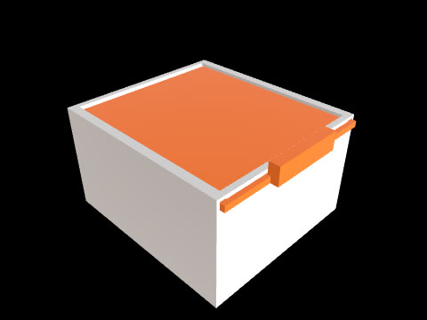
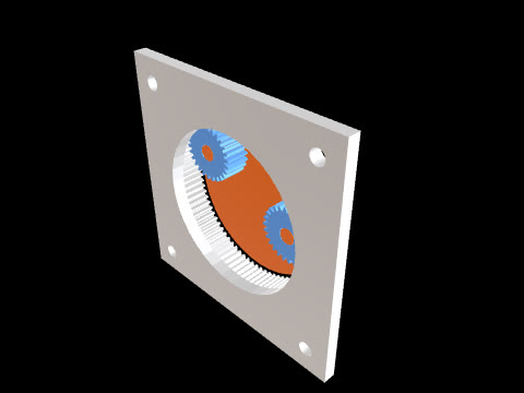
“내접 링기어, 유성기어 2개, 캐리어를 맞물린 조립 상태의 분리된 솔리드 4개로 만들어줘. 좌표계: 링기어 축은 Y축과 평행하고 (X=30, Z=25)를 지난다. 각도는 링 축 둘레로 XZ평면에서 +X에서 +Z 쪽으로 잰다. 유성기어 축도 Y축과 평행. 공통 치형: 인벌류트, 모듈 1.25, 압력각 20°, 전위 없음, 이뿌리 필렛은 자유. (1) 링기어: 잇수 84, 피치원 Ø105, 내치 이끝원 Ø102.5, 내치 이뿌리원 Ø108.125, 피치원 위 이홈 폭은 공칭 π·m/2 = 1.963. 내치는 Y=0~16 전 구간, 링 본체 외경 Ø122 (Y=0~16). 뒤쪽에 사각 플랜지: Y=-8~0, 150×150 (링 축 기준 X, Z 각 ±75, 변은 X축·Z축과 평행), 가운데 구멍 Ø100, Ø9 구멍 4개가 링 축 기준 (X, Z) = (±60, ±60)에서 Y방향 관통. 위상: 링은 0° 방향에 이홈 중심이 온다. (2) 유성기어 2개 (같은 형상): 잇수 26, 피치원 Ø32.5, 이끝원 Ø35, 이뿌리원 Ø29.375, 치폭 Y=0.5~15.5, Ø10 관통 보어. 백래시: 피치원 원호 이두께 π·m/2 - 0.08 = 1.883 (이 중심선에 대칭). 중심거리 36.25로 유성 1은 링 축에서 0° 방향, 유성 2는 135° 방향에 있다. 유성 1은 자기 축에서 바깥쪽(0° 방향)에 이 하나의 중심이 와서 링의 이홈에 들어가고, 유성 2는 바깥쪽(135° 방향)에 이홈 중심이 와서 그 자리에 오는 링의 이가 들어간다. (3) 캐리어 (한 솔리드): 링 축 위 원판 Ø100, Y=16.5~22.5. 두 유성기어 축 위에 Ø9.8 핀이 원판에서 Y=0.5까지 나와 유성 보어에 들어간다 (반경 틈 0.1). 원판 +Y쪽에 링 축 위 Ø20 축이 Y=22.5~45.”
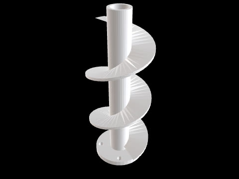
“스크루 컨베이어 축 한 개를 단일 솔리드로 만들어줘 (파이프, 플랜지, 나선 날개가 한 몸). 좌표계: 축은 Z축과 평행하고 (X=-10, Y=20)을 지난다. 각도 θ는 이 축 둘레로 XY평면에서 +X에서 +Y 쪽으로 잰다 (도 단위, 한 바퀴를 넘으면 계속 누적). (1) 파이프: 외경 Ø40, 내경 Ø30 관통, Z=0~300. (2) 플랜지: 외경 Ø100, Z=0~10 (파이프와 한 몸, 가운데는 Ø30 관통), Ø9 관통 구멍 4개가 Ø80 원 위 45°+k·90°. (3) 나선 날개 (오른나사, 피치 100, 축방향 두께 5, 2.5회전): 20 ≤ Z ≤ 270 인 모든 평면 Z=z에서 날개 단면은 반경 20~60, 각도 θ0(z) - 18° 부터 θ0(z) 까지의 환형 부채꼴이다. 여기서 θ0(z) = 3.6·(z - 20) (도). 즉 Z=20에서 부채꼴은 -18°~0°, Z가 100 올라갈 때마다 반시계 방향(+Z에서 볼 때)으로 한 바퀴 돌고, Z=270에서 162°~180°에서 끝난다. 날개 양 끝은 평면 Z=20과 Z=270으로 잘린 면이다. 날개 안쪽 가장자리는 파이프 외면과 한 몸.”
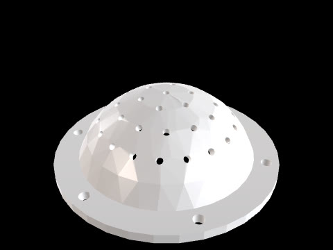
“구면 돔(샤워헤드형) 한 개를 단일 솔리드로 만들어줘. 좌표계: 돔 축은 Z축과 평행하고 (X=15, Y=-5)를 지난다. 구 중심 O = (15, -5, -20). 방위각은 돔 축 둘레로 XY평면에서 +X에서 +Y 쪽으로, 극각은 O에서 +Z 방향으로부터 잰다. (1) 셸: O 중심 외반경 60, 내반경 55인 구 껍질 중 Z≥0 부분 (Z=0 평면에서 잘림, 꼭대기 (15, -5, 40)). (2) 베이스 플랜지: 돔 축 위 환형판 외경 Ø144, 내경 Ø102, Z=-6~0 (셸 아래 끝과 한 몸). Ø6.6 관통 구멍 6개, 돔 축에서 반경 64, 방위각 30°+k·60°. (3) 셸 구멍: 모두 Ø4, 구 중심 O를 향하는 반경 방향 축으로 셸을 관통. - 꼭대기 구멍 1개: 극각 0° (돔 축 위). - 링 A: 극각 15°, 6개, 방위각 0°+k·60°. - 링 B: 극각 30°, 12개, 방위각 15°+k·30°. - 링 C: 극각 45°, 18개, 방위각 10°+k·20°.”
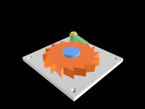
“Model a ratchet-and-pawl mechanism as five separate solids: base plate, shaft, ratchet wheel, pawl and pawl pin. Frame: all axes parallel to Z; angles in the XY plane from +X toward +Y about the ratchet axis, which passes through (10, 0). Base plate: X=-50..60, Y=-45..60, Z=0..6, with a Ø16 hole on the ratchet axis, a Ø6 hole on the pawl axis (below) and four Ø6.6 holes at (X, Y) = (-42, -37), (52, -37), (-42, 52), (52, 52), all through along Z. Shaft: Ø16 from Z=0 to Z=20 on the ratchet axis (sits in the base hole), with a collar Ø24 from Z=20 to Z=24. Ratchet wheel: 16 sawtooth teeth, Z=8..20, bore Ø16 on the shaft, and a spacer hub Ø26 from Z=6 to Z=8 under it. Tooth outline: tip radius 40, root radius 32. For k = 0..15 let a_k = 5° + k·22.5°. Tooth k has a RADIAL face along the ray at a_k from r=32 to r=40, and a straight back flank from the root point (r=32 at a_k) to the tip point (r=40 at a_(k+1)). So every radial face faces counter-clockwise (toward increasing angle) and the wheel can only turn clockwise seen from +Z. Pawl (Z=8..20): a straight bar, outline = quadrilateral (7.101, 33.135), (6.368, 41.511), (-29.714, 49.800), (-31.505, 42.003) (world XY), plus a boss Ø14 from Z=6 to Z=20 centred on the pawl axis (-30.609, 45.902), with a Ø6.2 hole on that axis. The edge (7.101, 33.135)-(6.368, 41.511) lies on the ray at 95° from the ratchet axis, so the pawl's end face bears flat on the radial face of tooth k=4; the bar's lower edge runs 1.2 above the back flank of tooth k=4. Pawl pin: Ø6 on the pawl axis from Z=0 to Z=20 (in the base hole), head Ø10 from Z=20 to Z=23.”
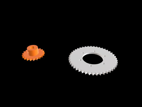
“Model two roller-chain sprockets for ISO 606 06B single-strand chain as two separate solids on a fixed centre distance; the chain itself is not modelled. Chain pitch p = 9.525, roller Ø6.35. Frame: both axes parallel to Z; sprocket A's axis passes through (20, -30), sprocket B's through (164, 78), so the line of centres from A to B points at 36.870° (centre distance 180). Both tooth plates occupy Z=0..5.3 (one chain line). Angles are measured in the XY plane from +X toward +Y about each sprocket's own axis. Tooth form, ISO 606 construction with these exact values: pitch diameter d = p / sin(180°/z). Around each roller centre on the pitch circle, a roller-seat arc of radius ri spans the seating angle, symmetric about the line from the roller centre to the sprocket centre. From each end of the seat arc a convex flank arc of radius re continues tangentially; its centre lies on the line from the roller centre through that seat-arc end, re beyond the end. The flanks are cut off by the tip circle da. Root diameter = d - 2ri. No tooth side chamfer. Sprocket A: 21 teeth, d = 63.908, ri = 3.30, seating angle 124°, re = 24, da = 68, root Ø57.308. Hub Ø32 from Z=5.3 to Z=25. Ø15 bore through Z=0..25 with a 5 wide keyway on the 90° side, floor 9.8 from the axis. A radial Ø5 set-screw hole at Z=15 runs from the hub surface into the bore on the 270° side. Phase: a TOOTH of A is centred on the 36.870° direction (pointing at B), so A's roller seats sit at 36.870° ± 8.571°. Sprocket B (plate type, no hub): 45 teeth, d = 136.546, ri = 3.30, seating angle 126°, re = 60, da = 141, root Ø129.946. Centre hole Ø60 through the plate; six Ø6.6 bolt holes through the plate on a Ø76 circle about B's axis at 0° + k·60°. Phase: a roller seat of B is centred on the 216.870° direction from B's axis (pointing at A).”
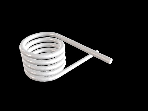
“Model a torsion spring as ONE solid (wire and legs in one piece). Frame: coil axis parallel to Z through (X=8, Y=-6); angles about it are measured in the XY plane from +X toward +Y. Wire: round, Ø3, swept along the path below (section perpendicular to the path). Coil: helix of radius 12 (wire centre), pitch 4, LEFT-hand, 4.75 turns, from Z=0 to Z=19. It starts at Z=0 on the 0° side, at (20, -6, 0). Left-hand: the angle DEcreases as Z increases (clockwise seen from +Z), angle = -90°·Z, so at Z=1 the wire centre is on the 270° side (8, -18, 1) and at Z=19 it ends on the 90° side at (8, 6, 19). Leg 1: straight, in the plane Z=0, tangent to the coil at its start: from (20, 34, 0) to the start point (20, -6, 0), i.e. it runs along -Y into the coil. Leg 2: straight, in the plane Z=19, tangent to the coil at its end: from the end point (8, 6, 19) along +X to (48, 6, 19). At both joints the wire is continuous (fill the joint with a Ø3 sphere); leg ends are flat.”
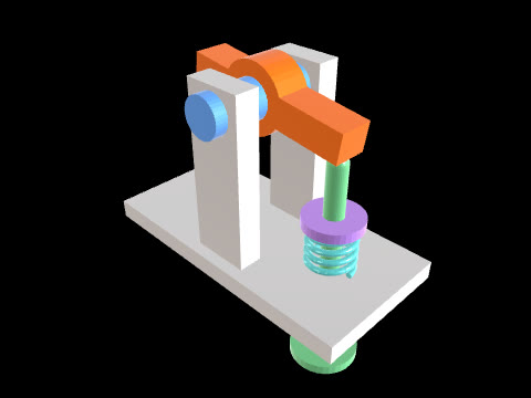
“Model a rocker-arm valve train as seven separate solids: pedestal, rocker shaft, rocker arm, valve, spring retainer, valve spring, pushrod. Frame: the rocker shaft axis is parallel to Y through X=0, Z=60; Z is up. Pedestal (one solid): base plate X=-60..60, Y=-30..30, Z=-8..0; two cheeks X=-12..12, Z=0..70, at Y=15..25 and Y=-25..-15, each with a Ø16 hole on the shaft axis. The base plate has a Ø8 hole for the valve stem and a Ø10 clearance hole for the pushrod (axes below), both through along Z. Rocker shaft: Ø16 along Y from Y=-30 to Y=30. Rocker arm (one solid, Y=-7..7), defined in an arm frame with origin on the shaft axis, arm x along the arm and arm z across it: a hub Ø28 with a Ø16 bore on the shaft, united with a beam x=-30..40, z=-6..6. The arm is rotated about the shaft axis by 8° so that its +X end goes DOWN: arm x = (cos8°, 0, -sin8°), arm z = (sin8°, 0, cos8°). Valve (one solid): vertical stem Ø8 whose axis is X=34.258, Y=0, from Z=-40 up to Z=45.087, capped by a hemisphere R4 centred at (34.258, 0, 45.087); this tip touches the arm's lower face (arm z=-6) at arm x=36. Head: disc Ø28 from Z=-44 to Z=-40. Spring retainer: disc Ø24, bore Ø8, Z=20..24 on the valve axis. Valve spring: round wire Ø2.5 swept along a helix around the valve axis, coil radius 9, right-hand, 4 turns from Z=1.25 to Z=18.75 (pitch 4.375), starting on the +X side of the valve axis; it rests on the base plate (Z=0) and touches the retainer (Z=20). Pushrod (one solid): vertical rod Ø6 with axis X=-25.158, Y=0, from Z=-40 up to Z=53.437, with a ball Ø8 centred at (-25.158, 0, 53.437); the ball touches the arm's lower face at arm x=-24.”
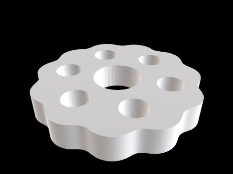
“Model a cycloidal-reducer disc as ONE solid. Frame: disc axis parallel to Z through (X=5, Y=-8); disc coordinates (x, y) are measured from that point with x parallel to world X and y parallel to world Y. Thickness Z=0..12. Outline: the curve for t = 0..2·pi (the standard cycloidal-disc profile for N = 12 ring pins on a pin circle of radius R = 40, pin radius Rr = 3, eccentricity E = 1.5, giving N-1 = 11 lobes): x(t) = R·cos t - Rr·cos(t + psi) - E·cos(N·t) y(t) = -R·sin t + Rr·sin(t + psi) + E·sin(N·t) psi(t) = atan2( sin((1-N)·t), R/(E·N) - cos((1-N)·t) ). At t = 0 this gives the point (35.5, 0): a valley (minimum radius 35.5) on +x; the lobe tips (radius 38.5) are halfway between valleys, the first at 16.364° (360°/22) from +x. Holes through Z=0..12: a Ø22 centre bore on the disc axis, and six Ø12 output-pin holes on a Ø48 circle at 30° + k·60° (angles from +x toward +y).”
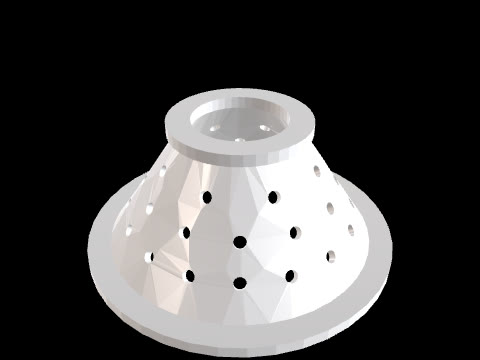
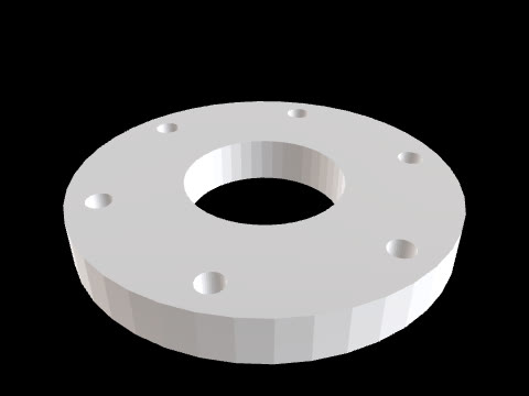
“Model a perforated conical shell as ONE solid. Frame: cone axis parallel to Z through (X=12, Y=12); azimuth phi is measured about that axis in the XY plane from +X toward +Y. Shell: the outer surface is the cone r_o(z) = 70 - (2/3)·z for z = 0..60 (radius 70 at Z=0, 30 at Z=60). The wall is 4 thick measured normal to that surface, so the inner surface is r_i(z) = 65.193 - (2/3)·z. The shell is cut by the planes Z=0 and Z=60. Bottom ring: annulus inner Ø124, outer Ø164, Z=-6..0. Top ring: annulus inner Ø48, outer Ø72, Z=60..66. Both are merged with the shell. Holes: Ø6, each drilled through the wall along the outward surface normal of the outer cone at a point P on the outer surface, i.e. along the direction (cos phi, sin phi, 2/3)/1.20185 (tilted up 33.69° from horizontal): - Row 1: P at z=15 (r_o=60), 16 holes at phi = 0° + k·22.5°. - Row 2: P at z=30 (r_o=50), 12 holes at phi = 15° + k·30°. - Row 3: P at z=45 (r_o=40), 8 holes at phi = 22.5° + k·45°.”
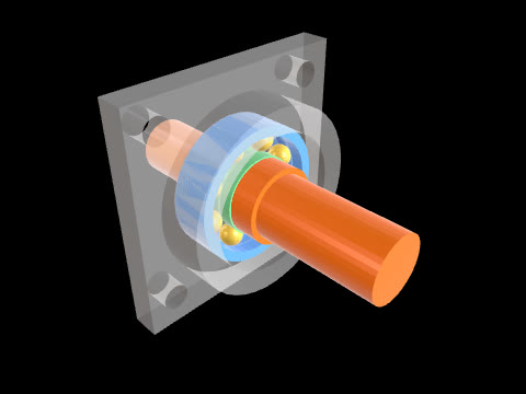
“깊은 홈 볼베어링이 들어간 하우징과 축을 조립 상태의 분리된 솔리드 12개(하우징, 외륜, 내륜, 볼 8개, 축)로 만들어줘. 좌표계: 공통 축은 X축과 평행하고 (Y=-15, Z=35)를 지난다. 각도는 축 둘레로 YZ평면에서 +Y에서 +Z 쪽으로 잰다. 아래 반경은 이 축에서 잰다. (1) 하우징 (한 솔리드): 사각 플랜지 X=0~10, 축 기준 Y·Z 각 ±40 (80×80, 변은 Y축·Z축과 평행), Ø9 볼트 구멍 4개가 축 기준 (Y, Z) = (±30, ±30)에서 X방향 관통. 보스 Ø64가 X=10~26. 보어: X=0~5는 Ø38 (외륜을 받치는 턱), X=5~26은 Ø47 (베어링 시트). (2) 외륜: 외경 Ø47, 내경 Ø40, X=5~19 (폭 14), X=5 면이 하우징 턱에 닿는다. (3) 내륜: 내경 Ø20, 외경 Ø27, X=5~19. 궤도홈: 외륜 안쪽과 내륜 바깥쪽에 반경 4.1의 원형 단면 홈. 홈 단면 원의 중심은 X=12 평면에서 반경 16.75의 원 위 (즉 반경 16.75 피치원을 도는 토러스로 두 링을 깎은 것). (4) 볼 8개: 각각 Ø8 구, 중심은 X=12, 반경 16.75의 피치원 위, 20° + k·45° (k=0..7) 방향. 즉 볼 하나의 중심이 20° 방향에 온다. 볼은 두 궤도홈과 0.1 틈. (5) 축 (한 솔리드): Ø20이 X=-30~19 (내륜 보어에 맞닿음, 하우징 턱 구멍 Ø38은 닿지 않고 지난다), 칼라 Ø26이 X=19~28 (X=19 면이 내륜 X=19 면에 닿는 축 턱), Ø22가 X=28~70. Ø22 구간에 0° 쪽(+Y쪽) 폭 6 키홈이 X=40~62 (끝은 직각), 키홈 바닥은 축에서 8.5.”
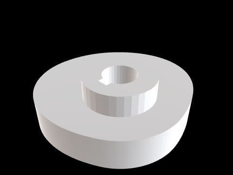
“Model a plate cam as ONE solid. Frame: cam axis parallel to Z through (X=10, Y=5); the polar angle phi is measured about that axis in the XY plane from +X toward +Y, in the cam's own (fixed) frame as modelled. Pitch curve (path of the centre of an in-line roller follower of radius 8): r(phi) = 38 + s(phi), with s in mm and phi in degrees: - 0 <= phi < 120: cycloidal rise, s = 14·(phi/120 - sin(2·pi·phi/120)/(2·pi)). - 120 <= phi < 180: dwell, s = 14. - 180 <= phi < 300: simple-harmonic return, s = 7·(1 + cos(pi·(phi-180)/120)). - 300 <= phi < 360: dwell, s = 0. Cam profile: the inner envelope of the roller circle (radius 8) moving along the pitch curve, i.e. the pitch curve offset inward by 8 along its normal (base circle radius 30, maximum radius 44). The profile is extruded from Z=0 to Z=15. Hub: Ø34 from Z=15 to Z=25 on the cam axis. Bore Ø16 through Z=0..25 with a 5 wide keyway on the 270° side (phi = 270°), full length, floor 10.3 from the axis.”
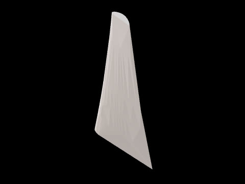
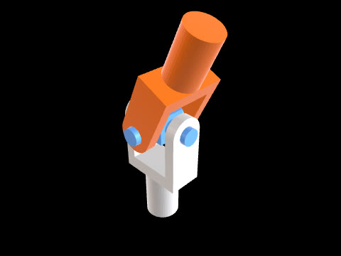
“유니버설 조인트(카르단)를 조립 상태의 분리된 솔리드 3개(요크 A, 요크 B, 십자축)로 만들어줘. 좌표계: 조인트 중심(십자축 중심) C = (10, -5, 60). (1) 십자축 (한 솔리드): C 중심의 정육면체 16×16×16 (변은 X, Y, Z축과 평행), 여기서 트러니언 4개: X방향 Ø10 원통이 C에서 X=-22~+22 (C 기준), Y방향 Ø10 원통이 C에서 Y=-22~+22 (C 기준). (2) 요크 A (입력, 축이 C 아래로 -Z 방향): 귀(ear) 2개는 두께 6의 판으로 X방향 트러니언을 잡는다. 귀는 C 기준 X=13~19 와 X=-19~-13, Y=-10~10, 아래로 Z=-26부터 위로 C 높이까지의 직사각형에 X축(트러니언 축) 둘레 R10 반원을 합친 윤곽. 귀마다 트러니언 축 위 Ø10.2 구멍. 두 귀는 바닥 블록 X=-19~19, Y=-10~10, Z=-34~-26 (모두 C 기준)으로 이어지고, 블록 아래 Ø20 축이 Z=-64~-34 (C 기준, 축은 C를 지나는 연직선). (3) 요크 B (출력): 요크 A와 같은 치수이지만 Y방향 트러니언을 잡고(귀는 C 기준 Y=13~19 와 Y=-19~-13), 축 방향은 w = (sin25°, 0, cos25°) = (0.42262, 0, 0.90631), 즉 C에서 위쪽으로 +X 쪽으로 25° 꺾여 있다 (십자축의 Y 트러니언 둘레로 25° 회전). 요크 B의 자기 좌표에서: 귀는 w 방향으로 -10~26 (트러니언 축 둘레 R10 반원 + 직사각형), 폭은 e = (cos25°, 0, -sin25°) 방향으로 ±10, 바닥 블록은 w 방향 26~34, e 방향 ±10, Y 방향 ±19, 축 Ø20이 w 방향 34~64. 모든 구멍과 트러니언 사이 반경 틈 0.1. 부품끼리 서로 파고들지 않는다.”
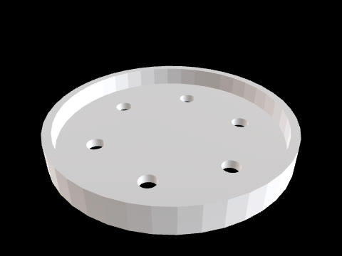
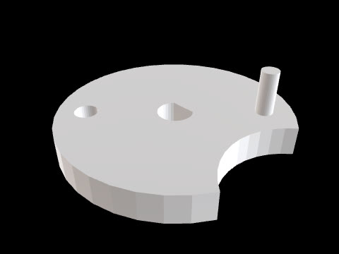
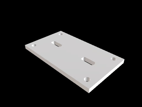
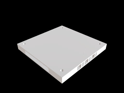
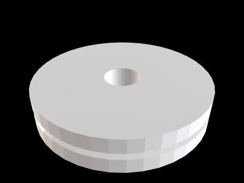
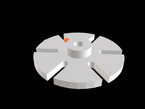
“Model a six-slot Geneva drive, assembled, as 2 separate solids: the driver (crank + drive pin) and the Geneva wheel. Frame: both axes parallel to Z; driver axis through (-20, 15), wheel axis through (40, 15) (centre distance 60). Angles in the XY plane from +X toward +Y about each part's own axis. Geneva wheel: plate Ø104, Z=0..8, with six radial slots 8.2 wide, one every 60°. Each slot runs along its centre line from the rim inward and ends in a semicircle whose centre is 28 from the wheel axis. Hub Ø30 on top, Z=8..18; Ø12 bore through Z=0..18. Driver: crank arm 14 wide, Z=-7..-1 (1 below the wheel), from the driver axis to the pin centre, 30 long between centres, both ends rounded R7. Hub Ø24 under the arm, Z=-20..-7, Ø10 bore through Z=-20..-1. Drive pin Ø8 on the arm end, from Z=-1 up to Z=8, one solid with the arm. Position: the crank points at 20° (measured from the line of centres, which points at 0°), so the pin centre is at (8.191, 25.261). The wheel is turned so that one slot's centre line passes through the pin centre: that slot points at 162.122° from the wheel axis (the pin centre is 33.423 from the wheel axis), and the other slots are at 162.122° + k·60°. The pin sits in the slot with 0.1 clearance each side.”
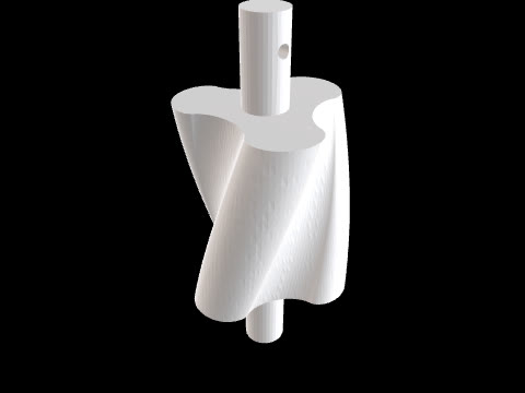
“3엽 루츠 블로어 로터 한 개를 단일 솔리드로 만들어줘. 좌표계: 로터 축은 Z축과 평행하고 (X=-20, Y=15)를 지난다. 단면 좌표 (x, y)는 이 축에서 잰 값 (x ∥ +X, y ∥ +Y), 각도는 +x에서 +y 쪽으로. Z=0 단면 윤곽: 피치원 반경 R=30 위를 반경 a=5의 원이 굴러 만드는 6개의 원호 (각각 피치원 60° 구간): - 엽(lobe) 원호 = 외전 사이클로이드: x = (R+a)·cosθ - a·cos((R+a)·θ/a), y = (R+a)·sinθ - a·sin((R+a)·θ/a), θ = 0~60°. 이 원호를 0°, 120°, 240°만큼 돌린 3개 (엽 끝 반경 40이 30°, 150°, 270° 방향). - 골(root) 원호 = 내전 사이클로이드: x = (R-a)·cosθ + a·cos((R-a)·θ/a), y = (R-a)·sinθ - a·sin((R-a)·θ/a), θ = 0~60°. 이 원호를 60°, 180°, 300°만큼 돌린 3개 (골 바닥 반경 20이 90°, 210°, 330° 방향). 로터 몸체: 이 윤곽을 Z=0에서 Z=90까지 나선형으로 밀어낸 것. 단면은 Z가 커질수록 +Z에서 볼 때 반시계 방향으로 돌아, Z=90에서 60° 돌아가 있다 (회전각 = 60°·Z/90, 균일). 축: Ø20 저널이 Z=-40~0 과 Z=90~130 (로터와 한 몸). Z=115에서 X방향 Ø6 크로스 구멍이 저널을 관통.”
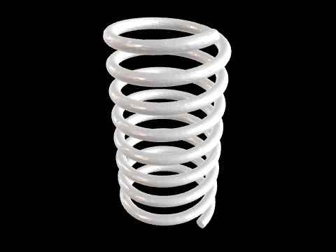
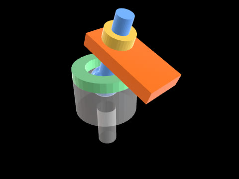
“볼 조인트를 조립 상태의 분리된 솔리드 5개(하우징, 캡, 볼 스터드, 레버 판, 너트)로 만들어줘. 좌표계: 볼 중심 C = (15, -10, 30). 하우징 축은 C를 지나는 연직선(Z축과 평행). 스터드 축 방향 s = (sin20°, 0, cos20°) = (0.34202, 0, 0.93969), 즉 연직에서 +X 쪽으로 20° 기울어 있다. t = (cos20°, 0, -sin20°) 는 s에 수직인 XZ평면 안 방향. (1) 하우징 (한 솔리드): C 축 위 원통 Ø50, Z=5~35, 아래로 Ø16 생크가 Z=-30~5. 내부: C 중심 반경 12.5의 구면 소켓 (C 아래쪽 반구) 과 Ø25 원통 보어 Z=30~35. (2) 캡 (한 솔리드): C 축 위 원판 Ø50, Z=35~43. 안쪽은 C 중심 반경 12.5 구면으로 깎이고, 가운데 Ø30 관통 구멍. (3) 볼 스터드 (한 솔리드): 볼 Ø25 (중심 C), 목 Ø14가 s 방향으로 C에서 거리 0~30, 생크 Ø12가 거리 30~60 (모두 s 축 위). (4) 레버 판: s에 수직인 판, s 방향 거리 30~40 (목의 어깨 면에 앉는다). 판 안에서 t 방향 -15~45, Y 방향 ±15. 생크가 지나는 Ø12 구멍이 s 축 위. (5) 너트: s 축 위 원통 Ø22, 보어 Ø12, s 방향 거리 40~48 (레버 판 위에 닿는다). 볼은 소켓·캡의 구면과 닿고 모든 부품은 서로 파고들지 않는다.”
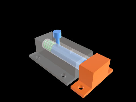
“스프링 걸쇠(슬라이드 래치)를 빗장이 걸림쇠에 들어간 상태로 분리된 솔리드 4개(하우징, 빗장, 압축 스프링, 걸림쇠)로 만들어줘. 좌표계: 빗장 축은 X축과 평행하고 (Y=12, Z=10)을 지난다. 축 둘레 각도는 YZ평면에서 +Y에서 +Z 쪽으로 잰다. (1) 하우징 (한 솔리드): 블록 X=0~60, Y=0~24, Z=0~20. 바닥 부착판 Z=0~3이 X=0~60, Y=-10~34, Z방향 Ø4.5 구멍 4개 (X, Y) = (10, -5), (50, -5), (10, 29), (50, 29). 빗장 축 위 Ø12.2 보어가 X=4~60 (X=60 쪽 열림, X=0~4는 막힌 끝벽). 윗면 슬롯: 폭 4.2 (Y=9.9~14.1), X=18~44 (끝은 직각), 보어에서 윗면 Z=20까지 관통. (2) 빗장 (한 솔리드): Ø12 원통이 빗장 축 위 X=20~70. 손잡이 Ø4 핀이 X=24에서 빗장 축부터 +Z로 Z=26까지 (슬롯을 지난다), 그 위 Ø8 노브가 Z=26~32. (3) 압축 스프링: 선경 Ø1.6 (원형 단면), 코일 평균 지름 Ø9 (선 중심이 축에서 반경 4.5), 오른감기, 4회전. 선 중심의 나선은 X=4.8에서 X=19.2까지 (피치 3.6), 끝은 연마하지 않은 채 잘린 그대로이고, 선이 X=4 끝벽과 X=20 빗장 뒷면에 닿는다. 시작점: X=4.8에서 선 중심은 축의 +Z쪽 (Y=12, Z=14.5). 오른감기이므로 X가 커질수록 선 중심 각도가 +Y에서 +Z 쪽 방향으로 증가한다 (X=5.7에서 180°, 즉 (Y=7.5, Z=10)). (4) 걸림쇠 (한 솔리드): 블록 X=64~78, Y=0~24, Z=0~20, 바닥판 Z=0~3이 X=64~78, Y=-10~34, Z방향 Ø4.5 구멍 2개 (71, -5), (71, 29). 빗장 축 위 Ø12.4 막힌 구멍 X=64~74. 빗장 끝(X=70)이 6 들어가 있다.”
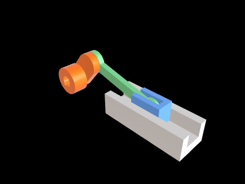
“Model an in-line slider-crank mechanism, assembled at one crank angle, as 4 separate solids: crank, connecting rod, slider and guide. Frame: the crank axis is parallel to Y through X=10, Z=5. The slider moves along the line parallel to X through Z=5 (in line with the crank axis). Angles are measured in the XZ plane from +X toward +Z. Crank (one solid): hub Ø30 on the crank axis from Y=-16 to Y=0; arm Y=0..8, a straight 24 wide bar from the crank axis to the crank-pin centre 25 away, both ends rounded R12 about those two centres; crank pin Ø10 from Y=8 to Y=15. Ø12 bore on the crank axis through Y=-16..8 with a 4 wide keyway pointing away from the crank pin (230°), floor 7.8 from the axis. Position: the crank points at 50°, so the crank-pin centre is at X=26.070, Z=24.151. Connecting rod: Y=8.2..14.2, 80 between centres. Big eye Ø24 with a Ø10.2 hole on the crank pin; small eye Ø18 with a Ø8.2 hole on the wrist pin; the eyes are joined by a straight shank 10 wide centred on the line between the centres. Slider (one solid, wrist pin included): the wrist-pin centre is on the slide line at X=103.744 (so the rod length is exactly 80). Block X=87.744..119.744 (wrist pin -16..+16), Z=-6..16, Y=2..20. A slot for the rod, Y=7.7..14.7, runs through the full block height and from the block's -X face to X=114.744 (wrist pin +11), leaving a 5 thick bridge at the +X end. Wrist pin Ø8 along Y from Y=2 to Y=20 on the wrist-pin centre, bridging the slot. Guide (one solid): base plate X=60..150, Y=-6..28, Z=-16..-6 (the slider rests on its top face Z=-6), and two side walls X=60..150, Z=-6..8, at Y=-6..2 and Y=20..28, touching the slider's Y=2 and Y=20 faces.”
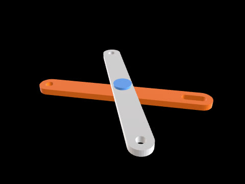
“Model a scissor link, assembled, as 3 separate solids: bar A, bar B and the pivot pin. Frame: the pivot axis is parallel to Z through X=15, Y=20. Angles in the XY plane from +X toward +Y. Distances along a bar are measured from the pivot axis along that bar's direction. Both bars have the same stadium outline in plan: 16 wide, straight sides, semicircular ends of radius 8 centred at -60 and +60 along the bar (overall length 136), with a Ø8.2 pivot hole on the pivot axis. Bar A: 5 thick, Z=0..5, its direction points at 35°. It has a Ø6.2 hole at -60 and, at the + end, a slot 6.2 wide along the bar with semicircular ends whose centres are at +48 and +60. Bar B: 5 thick, Z=5.2..10.2 (0.2 above bar A), its direction points at 145°, so the bars cross at 110°. It has Ø6.2 holes at -60 and +60. Pivot pin: Ø8 shank on the pivot axis from Z=-4 to Z=10.2, head Ø14 from Z=10.2 to Z=12.2 seated on bar B's top face, and a Ø2.5 split-pin hole through the shank along the X direction at Z=-1.5.”
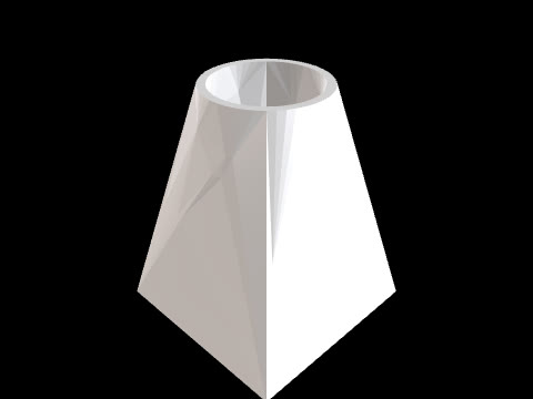
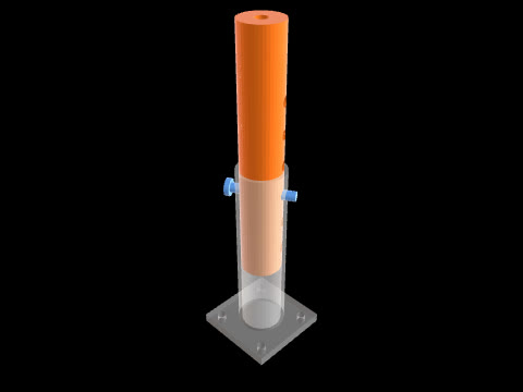
“텔레스코픽 원형 파이프 2개를 크로스 핀으로 고정한 조립체를 분리된 솔리드 3개(바깥 파이프, 안쪽 파이프, 핀)로 만들어줘. 좌표계: 두 파이프의 공통 축은 Z축과 평행하고 (X=12, Y=-8)을 지난다. 각도는 XY평면에서 +X에서 +Y 쪽으로 잰다. 핀 축은 Z=130 높이에서 파이프 축과 직교하며 방향 d = (cos30°, sin30°, 0) = (0.86603, 0.5, 0). 아래에서 s는 파이프 축에서 d 방향으로 잰 거리. (1) 바깥 파이프 (한 솔리드): 외경 Ø40, 내경 Ø34, Z=0~150. 아래 끝에 사각 받침판 Z=-8~0, 70×70 (파이프 축 기준 X, Y 각 ±35, 변은 X축·Y축과 평행), 받침판은 막혀 있고 Ø7 구멍 4개가 파이프 축 기준 (±25, ±25)에서 Z방향 관통. 핀 구멍 Ø8.4가 Z=130에서 d 방향으로 양쪽 벽 관통. (2) 안쪽 파이프 (한 솔리드): 외경 Ø33.8 (바깥 파이프와 반경 틈 0.1), 내경 Ø27.8, Z=60~260. 위 끝은 두께 8의 마개로 막혀 있다 (Z=252~260, 가운데 Ø10 구멍 관통, 속 빈 부분은 Z=60~252). 핀 구멍 Ø8.4 쌍 6개가 d 방향으로 양쪽 벽 관통, 높이는 아래 끝에서 20 + k·25 (k=0..5), 즉 Z=80, 105, 130, 155, 180, 205. 아래에서 세 번째 구멍(k=2, Z=130)이 바깥 파이프의 핀 구멍과 맞춰져 있다. (3) 핀 (한 솔리드): Ø8 축부가 핀 축 위 s=-24~27, 머리 Ø14가 s=-28~-24 (머리는 d의 음의 쪽, 머리 안쪽 면은 바깥 파이프 표면에서 떨어져 있다). 끝 쪽 s=24에 클립용 Ø2.5 구멍이 Z방향으로 축부를 관통.”
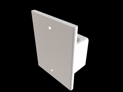
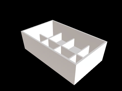
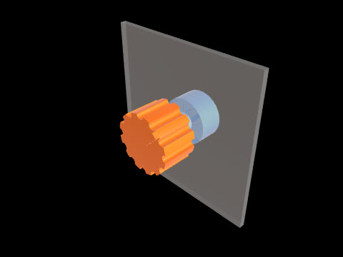
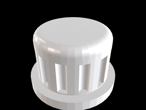
“Model a control knob on a D-shaft potentiometer mounted in a panel, assembled, as 4 separate solids: panel, potentiometer (body, bushing and shaft as one solid), knob, set screw. Frame: the shaft axis is parallel to Y through X=-30, Z=40; the knob is on the -Y side of the panel. Angles are measured about the shaft axis in the XZ plane from +X toward +Z; radii are from the shaft axis. Panel: plate Y=0..3, X=-70..10, Z=0..80, with a Ø10 hole on the shaft axis. Potentiometer (one solid): body Ø24 from Y=3 to Y=15 (against the panel's back face), bushing Ø10 from Y=0 to Y=3 filling the panel hole, shaft Ø6 from Y=0 to Y=-20. D-flat: from Y=-10 to the shaft tip Y=-20 the shaft is cut by a plane 1.5 from the axis whose outward normal points at 225°. Knob (one solid): cylinder Ø30 from Y=-6 to Y=-24 (6 clear of the panel). Twelve grip flutes: semicircular grooves R2 along Y over the full knob length, their centres on radius 15 at 0° + k·30°. Pointer: a raised rib on the front face, 3 wide, Y=-26..-24, running radially from radius 5 to radius 15 along the 45° direction (diametrically opposite the flat). Blind bore Ø6.1 on the axis from Y=-6 to Y=-21. A Ø3 radial set-screw hole at Y=-14 runs from the bore to the knob surface along the 225° direction. Set screw: a plain Ø3 cylinder in that hole, on the 225° line at Y=-14, from radius 1.5 (its flat end bearing on the shaft's D-flat) out to radius 12 (3 below the knob surface).”
나만의 부품을 만들어볼까요?
부품을 설명하고 결과를 검토한 뒤, 수정하여 내보내세요.