

テキスト・画像入力
寸法・パラメータ調整
チャットで修正・履歴管理
STEP・STL出力
作りたい製品から始めましょう。
ケースから機械部品まで、CADモデルの作例をそろえました。モデルを開いて形状を確認し、必要な寸法や構造に変更できます。
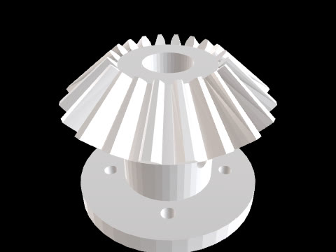
“Bevel gear with straight teeth. Pitch cone angle 45 degrees, 20 teeth, module 3mm. Face width 20mm. Shaft bore 15mm with set screw. Hub diameter 30mm, length 25mm. Mounting flange with 4 M4 holes on 40mm PCD.”
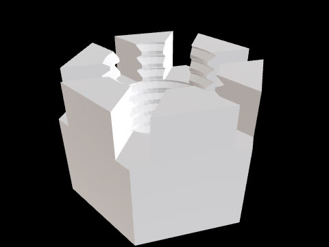
“Design a castle nut (DIN 935). M16 thread, height 18mm, width across flats 24mm. 6 castellated crown slots for cotter pin retention. Slot depth 6mm, width 4mm. Hex body with through bore.”
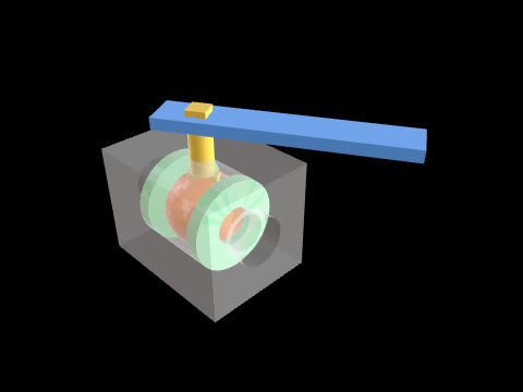 6部品
6部品“레버식 볼밸브를 30° 열린 상태로, 분리된 솔리드 6개(몸체, 볼, 시트 링 2개, 스템, 핸들)로 만들어줘. 좌표계: 유로 축 = X축, 볼 중심 = 원점, 스템 축 = Z축. 방향 d = (cos30°, sin30°, 0) = (0.86603, 0.5, 0) 은 볼 구멍과 핸들 방향, e = (-0.5, 0.86603, 0) 은 그에 수직인 수평 방향. (1) 몸체 (한 솔리드): 블록 X=-40~40, Y=-30~30, Z=-30~30. 유로 구멍 Ø20이 X방향 전장 관통, 양 끝에 배관용 카운터보어 Ø26 (X=30~40, X=-40~-30). 내부 캐비티: X축 위 원통 Ø48, X=-22~22 (닫힌 공간). 스템 구멍 Ø12가 Z축 위 캐비티에서 윗면 Z=30까지. (2) 볼: 구 Ø40 (중심 원점). 볼 구멍 Ø20이 d 방향 축으로 관통. 윗면에 스템 탱 홈: d 방향으로 길고, e 방향 폭 6 (±3), Z=15에서 구 표면까지 (d 방향으로 전장 관통). (3) 시트 링 2개: 각각 X축 위 환형 원통 외경 Ø48, 내경 Ø20, 하나는 X=15~22, 다른 하나는 X=-22~-15. 볼과 닿는 쪽은 볼 구면(Ø40)으로 깎여 볼에 맞닿는다. (4) 스템 (한 솔리드): 탱 = d 방향 길이 16 (±8), e 방향 두께 6 (±3), Z=15~21인 직육면체 (볼의 홈 안). 축 Ø12가 Z=21~45. 윗끝 사각 10×10 (변은 d, e 방향과 평행)이 Z=45~55. (5) 핸들 (한 솔리드): Z=46~52의 판. 스템 축 기준 d 방향으로 -20부터 +100까지, e 방향 폭 20 (±10), 스템 사각이 끼는 10×10 사각 구멍 (변은 d, e와 평행). 즉 핸들은 볼 구멍과 같은 30° 방향을 가리킨다.”
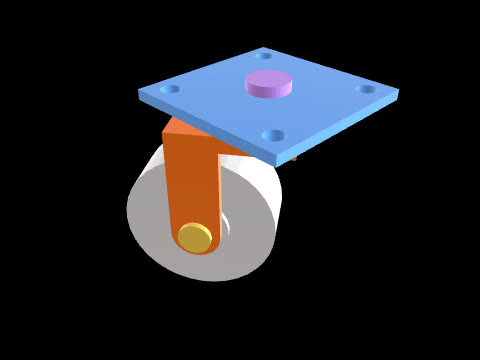 7部品
7部品“Model a swivel caster as seven separate solids: top plate, thrust washer, kingpin bolt, nut, fork, wheel, axle. Frame: the kingpin (swivel) axis is the Z axis; the floor is Z=0 and the wheel touches it. Top plate: X=-40..40, Y=-40..40, Z=100..105 (edges parallel to X and Y), Ø12 hole on the Z axis and four Ø9 holes at (±30, ±30), all through along Z. Thrust washer: Ø40, bore Ø12, Z=92..100, on the Z axis. Kingpin bolt: shank Ø12 from Z=78 to Z=105 on the Z axis, head Ø20 from Z=105 to Z=110. Nut: Ø20 cylinder, bore Ø12, Z=78..84. Fork, one solid, described in a fork frame whose origin is on the Z axis: its x axis is the horizontal direction (cos35°, sin35°, 0), its y axis is (-sin35°, cos35°, 0), z = world Z. Crown plate: x=-42..15, y=-23..23, Z=84..92, with a Ø12 hole on the Z axis. Two legs, 5 thick, at y=18..23 and y=-23..-18; each leg (in the x-Z plane) is the rectangle x=-42..-18, Z=37.5..84 united with a disc R12 centred on the axle point (x=-30, Z=37.5), and has a Ø10 axle hole there. So the axle sits 30 behind the kingpin toward the 215° direction, at world (X, Y) = (-24.575, -17.207), Z=37.5. Wheel: axis along the fork y axis through the axle point. Tyre Ø75 over y=-15..15, hub Ø30 over y=-18..18 (the hub faces touch the legs), bore Ø10. Axle: Ø10 along the fork y axis from y=-26 to y=26 through the legs and wheel, with Ø16 heads over y=23..26 and y=-26..-23 bearing on the outer faces of the legs.”
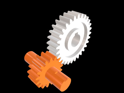 2部品
2部品“Model a meshing spur gear pair as two separate solids. Frame: both gear axes are parallel to the X axis. The pinion axis passes through Y=20, Z=-10; the wheel axis passes through Y=99.674, Z=36, so the line of centres runs 30° from +Y toward +Z (centre distance 92). Angular positions about each axis are measured in the YZ plane from +Y toward +Z. Tooth form for both: involute, module 4, pressure angle 20°, no profile shift, addendum 1.0m, root diameter = pitch diameter - 2.5m, root fillets free. Backlash: circular tooth thickness on the pitch circle = pi*m/2 - 0.15 = 6.133, symmetric about the tooth centre line. Both toothed widths span X=0..30. Pinion (a gear shaft, one solid): 17 teeth, pitch Ø68, outside Ø76, root Ø58. Shaft Ø30 from X=-50 to X=0 and from X=30 to X=75. The X=30..75 end has a square-ended keyway 8 wide from X=48 to X=75 on the 90° side (+Z side of the shaft), floor 11 from the pinion axis. Phase: the pinion has a tooth SPACE centred on the 30° direction (toward the wheel). Wheel: 29 teeth, pitch Ø116, outside Ø124, root Ø106. Both side faces are recessed: an annular pocket from Ø56 out to Ø88, 9 deep, is cut into the X=0 face (X=0..9) and into the X=30 face (X=21..30), leaving a web X=9..21. Hub Ø56 from X=-10 to X=30 (it sticks out 10 on the -X side). Ø32 bore through X=-10..30 with a 10 wide keyway on the 90° side over the full length, keyway floor 20.3 from the wheel axis. A radial Ø6.8 set-screw hole at X=-5 runs from the hub surface into the bore on the 0° side (+Y side). Phase: the wheel has a TOOTH centred on the 210° direction from its own axis (toward the pinion), which sits in the pinion's tooth space.”
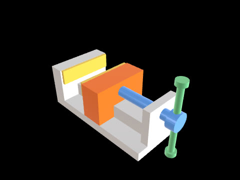 6部品
6部品“벤치 바이스를 조립 상태의 분리된 솔리드 6개(몸체, 이동 조, 고정 조 판, 이동 조 판, 스크루, 핸들)로 만들어줘. 좌표계: 조(jaw)가 X방향으로 움직이고, 스크루 축은 X축과 평행한 (Y=0, Z=45) 직선. 바닥면 Z=0. (1) 몸체 (한 솔리드): 베이스 판 X=-60~100, Y=-40~40, Z=0~12. 고정 조 블록 X=-60~-40, Y=-40~40, Z=12~60. 가이드 바 X=-40~90, Y=-15~15, Z=12~30. 엔드 판 X=90~100, Y=-25~25, Z=12~60, 스크루 축 위에 Ø14 구멍이 X방향 관통. (2) 고정 조 판: X=-40~-36, Y=-38~38, Z=40~60 (고정 조 블록의 +X면에 붙는다). (3) 이동 조 (한 솔리드): 블록 X=5.5~35.5, Y=-40~40, Z=12~60에서 가이드를 감싸는 채널 Y=-15~15, Z=12~30을 X방향 전장으로 뺀 형상 (채널 윗면이 가이드 윗면 Z=30에, 옆면이 가이드 옆면에 닿는다). +X면(X=35.5)에서 스크루 축 위로 Ø14 막힌 구멍, 깊이 12 (X=23.5~35.5, 바닥 평평). (4) 이동 조 판: X=1.5~5.5, Y=-38~38, Z=40~60 (이동 조의 -X면에 붙는다). 따라서 두 조 판 사이 벌림(X=-36~1.5)은 37.5. (5) 스크루 (한 솔리드, 나사산은 생략한 원통): Ø14가 X=23.5~110 (끝이 이동 조 막힌 구멍 바닥에 닿고 엔드 판 구멍을 지난다), 머리 Ø24가 X=110~122. 머리에 X=116에서 Z방향 Ø8 관통 구멍. (6) 핸들 (한 솔리드): Ø8 봉이 머리 구멍을 지나 Z방향으로, 축 (X=116, Y=0), Z=0~90. 양 끝에 노브 Ø14: Z=-6~0과 Z=90~96.”
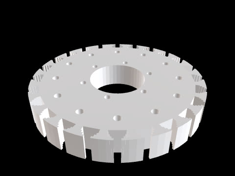
“Turbine rotor disc. Outer diameter 250mm, bore 80mm, thickness 35mm. 24 fir-tree blade attachment slots around rim, 15mm deep with 3-step profile. 6 assembly bolt holes (M8) on 100mm bolt circle. 12 lightening holes (10mm) on 180mm circle.”
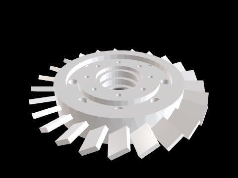
“Design a gas turbine compressor blisk (bladed integrated disk). OD 300mm, bore 80mm. Hub 140mm diameter, 50mm thick. 24 integral blades 40mm height, 30mm chord, 35° stagger. 3 labyrinth seal teeth in bore. 8 bolt holes M8 on 110mm PCD. 8 lightening holes.”
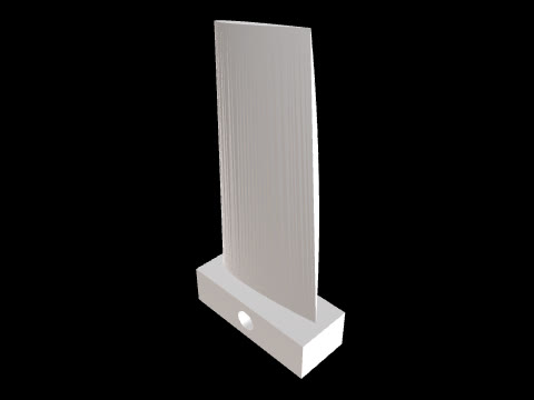
“NACA 대칭 익형 단면 3개를 로프트한 비틀린 블레이드와 루트 블록을 단일 솔리드로 만들어줘. 좌표계: 블레이드 스팬 방향 = +Z, 비틀림 축 = Z축 (각 단면의 1/4 시위점이 Z축 위에 있다). 단면 정의 (단면 평면 Z=z 안의 국부 좌표 x, y): 시위선은 국부 x축 위, 앞전(LE)은 x = -c/4, 뒷전(TE)은 x = 3c/4. 두께 분포는 NACA 4자리 대칭식 y = ±5·t·c·(0.2969·√ξ - 0.1260·ξ - 0.3516·ξ² + 0.2843·ξ³ - 0.1036·ξ⁴), ξ = (x + c/4)/c (0~1), 뒷전은 뾰족하게 닫힌다. 국부 좌표는 +Z에서 내려다볼 때 반시계 방향으로 비틀림각만큼 돌린 뒤 월드에 놓는다 (국부 x축 = (cosθ, sinθ, 0)). - 단면 1: Z=0, 시위 c=60, 두께비 t=0.15 (NACA 0015), 비틀림 θ=0°. - 단면 2: Z=60, c=48, t=0.12 (NACA 0012), θ=15°. - 단면 3: Z=120, c=36, t=0.10 (NACA 0010), θ=30°. 블레이드 = 세 단면을 순서대로 지나는 매끄러운 로프트 (Z=0~120, 끝은 평평). 루트 블록: X=-20~50, Y=-14~14, Z=-20~0 직육면체 (블레이드 루트 면이 그 윗면에 붙는다), Y방향 관통 Ø10 구멍, 축 (X=15, Z=-10).”
設計を重ね、 モデルを完成させる。
寸法や形状を調整し、過去のバージョンを確認しながら、試作に向けて設計を仕上げられます。実際の操作画面で、寸法変更、チャットでの修正、STEPファイルの書き出しをご覧ください。
設計を始める01 / 04