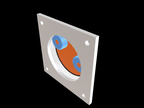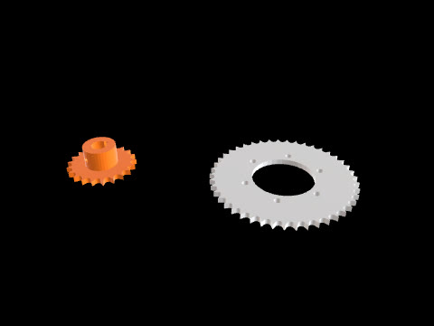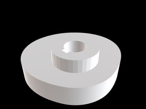
かみ合う平歯車ペア
CADlingoが下のプロンプトから生成したモデルです。スタジオで開くと、3Dでの確認、断面表示、寸法の調整ができます。
プロンプト
Model a meshing spur gear pair as two separate solids. Frame: both gear axes are parallel to the X axis. The pinion axis passes through Y=20, Z=-10; the wheel axis passes through Y=99.674, Z=36, so the line of centres runs 30° from +Y toward +Z (centre distance 92). Angular positions about each axis are measured in the YZ plane from +Y toward +Z. Tooth form for both: involute, module 4, pressure angle 20°, no profile shift, addendum 1.0m, root diameter = pitch diameter - 2.5m, root fillets free. Backlash: circular tooth thickness on the pitch circle = pi*m/2 - 0.15 = 6.133, symmetric about the tooth centre line. Both toothed widths span X=0..30. Pinion (a gear shaft, one solid): 17 teeth, pitch Ø68, outside Ø76, root Ø58. Shaft Ø30 from X=-50 to X=0 and from X=30 to X=75. The X=30..75 end has a square-ended keyway 8 wide from X=48 to X=75 on the 90° side (+Z side of the shaft), floor 11 from the pinion axis. Phase: the pinion has a tooth SPACE centred on the 30° direction (toward the wheel). Wheel: 29 teeth, pitch Ø116, outside Ø124, root Ø106. Both side faces are recessed: an annular pocket from Ø56 out to Ø88, 9 deep, is cut into the X=0 face (X=0..9) and into the X=30 face (X=21..30), leaving a web X=9..21. Hub Ø56 from X=-10 to X=30 (it sticks out 10 on the -X side). Ø32 bore through X=-10..30 with a 10 wide keyway on the 90° side over the full length, keyway floor 20.3 from the wheel axis. A radial Ø6.8 set-screw hole at X=-5 runs from the hub surface into the bore on the 0° side (+Y side). Phase: the wheel has a TOOTH centred on the 210° direction from its own axis (toward the pinion), which sits in the pinion's tooth space.
モデル情報
- 全体サイズ
- 125 × 179.4 × 145.9 mm
- ボディ数
- 2
- 体積
- 407.8 cm³
- スタジオで調整可能
- 1個の寸法