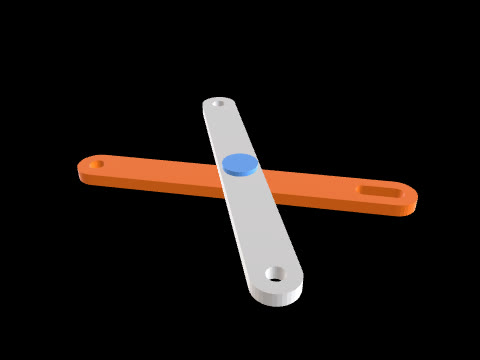
曲柄滑块机构
这是 CADlingo 根据下方提示词生成的模型。在工作台中打开,即可在 3D 中查看、检查剖面并调整尺寸。
提示词
Model an in-line slider-crank mechanism, assembled at one crank angle, as 4 separate solids: crank, connecting rod, slider and guide. Frame: the crank axis is parallel to Y through X=10, Z=5. The slider moves along the line parallel to X through Z=5 (in line with the crank axis). Angles are measured in the XZ plane from +X toward +Z. Crank (one solid): hub Ø30 on the crank axis from Y=-16 to Y=0; arm Y=0..8, a straight 24 wide bar from the crank axis to the crank-pin centre 25 away, both ends rounded R12 about those two centres; crank pin Ø10 from Y=8 to Y=15. Ø12 bore on the crank axis through Y=-16..8 with a 4 wide keyway pointing away from the crank pin (230°), floor 7.8 from the axis. Position: the crank points at 50°, so the crank-pin centre is at X=26.070, Z=24.151. Connecting rod: Y=8.2..14.2, 80 between centres. Big eye Ø24 with a Ø10.2 hole on the crank pin; small eye Ø18 with a Ø8.2 hole on the wrist pin; the eyes are joined by a straight shank 10 wide centred on the line between the centres. Slider (one solid, wrist pin included): the wrist-pin centre is on the slide line at X=103.744 (so the rod length is exactly 80). Block X=87.744..119.744 (wrist pin -16..+16), Z=-6..16, Y=2..20. A slot for the rod, Y=7.7..14.7, runs through the full block height and from the block's -X face to X=114.744 (wrist pin +11), leaving a 5 thick bridge at the +X end. Wrist pin Ø8 along Y from Y=2 to Y=20 on the wrist-pin centre, bridging the slot. Guide (one solid): base plate X=60..150, Y=-6..28, Z=-16..-6 (the slider rests on its top face Z=-6), and two side walls X=60..150, Z=-6..8, at Y=-6..2 and Y=20..28, touching the slider's Y=2 and Y=20 faces.
模型信息
- 整体尺寸
- 155 × 44 × 52.2 mm
- 实体数
- 4
- 体积
- 84.0 cm³
- 可在工作台中调整
- 3 个尺寸